
Date:2026-05-23 Click:144
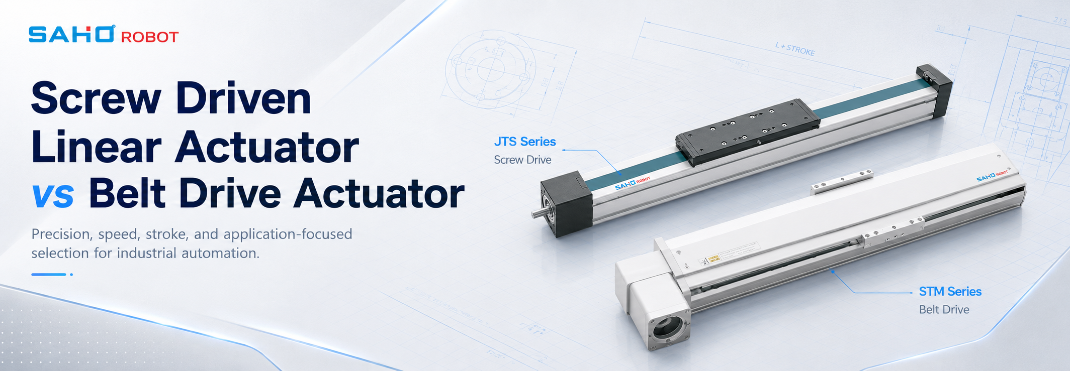
In automated equipment, a screw driven linear actuator is often compared with a belt drive module because both support linear motion, but they serve different machine goals. Therefore, the drive structure should be selected according to precision, stroke, speed, load, rigidity, and service access.
For example, a compact inspection station may need repeatable stopping and low vibration. Meanwhile, a tray transfer unit may need long travel and fast point-to-point movement. As a result, both drive types can be correct when they match the station function.
Motion Requirements Should Lead the Selection
First, actuator selection should start with the process. A loading station, lifting axis, dispensing head, inspection camera, or small assembly unit may all require linear motion. However, each station creates a different demand on the mechanical axis.
For instance, a short positioning move may need stable final accuracy more than maximum speed. Meanwhile, a long transfer move may need smooth acceleration and enough travel length. Therefore, the same production line can use both screw drive and belt drive modules in different positions.
In addition, the moving load must include more than the workpiece. Tool plates, grippers, sensors, brackets, vacuum lines, cable carriers, and future tooling changes can all increase mass. Because of this, the motion review should use the full moving assembly, not only the part weight.
Next, the installation direction matters. Horizontal axes mainly handle inertia and friction. Vertical axes also handle gravity, power-off behavior, and safety during emergency stop. As a result, vertical applications require careful review of braking, holding force, and mechanical protection.
Finally, the surrounding machine frame should be reviewed at the same time. A strong actuator cannot perform well on a weak or uneven mounting base. Therefore, frame rigidity, mounting surface quality, and fastening positions remain part of the axis decision.
How Screw Drive and Belt Drive Motion Differ
Generally, a screw drive structure converts rotary motor motion into linear movement through a screw and nut mechanism. This direct conversion supports controlled positioning, firm movement, and useful thrust in compact equipment.
By contrast, a belt drive structure transfers motion through a timing belt and pulley system. This structure often supports longer travel and higher transfer speed. Therefore, it often appears in loading, unloading, shuttle, and gantry movement.
However, the comparison should not become a simple rule of accuracy versus speed. Real equipment also depends on acceleration, settling time, payload balance, stroke length, mounting direction, cable routing, and working environment.
For example, a belt module may move quickly over a long distance. Still, a process that needs stable end-position control may require slower tuning. Meanwhile, a screw drive module may deliver stable positioning in a compact station, yet it may not be the natural choice for a very long travel axis.
In other words, the useful question is not which structure is stronger in general. The better question is which structure supports the station goal with the least compromise. This practical view prevents overbuilding one axis and undersizing another.
Where Screw Drive Modules Fit Best
First, screw drive modules often fit compact stations that require repeatable stopping. Inspection, probing, dispensing, alignment, light pressing, small-part assembly, and controlled vertical approach can all benefit from this behavior.
For example, a vision inspection head must settle before image capture. If the axis vibrates after each move, the station may need extra waiting time. Therefore, stable stopping can matter more than headline speed.
In another case, a dispensing nozzle may need a consistent path and controlled travel speed. Uneven motion can change bead width, coating thickness, or process repeatability. As a result, rigidity and smooth control become important.
Moreover, screw drive modules are useful when the station layout has limited space. A compact body can reduce bracket length, shorten tooling distance, and support a cleaner machine envelope. However, compact design still requires enough load capacity and stiffness.
In short, screw drive motion is often selected when final position, compact structure, and controlled movement are central to the process. This makes it especially useful for short-to-medium travel axes inside precision equipment.

JTS80 supports compact positioning layouts where short-to-medium travel and controlled movement are required.
Where Belt Drive Modules Fit Best
Meanwhile, belt drive modules often fit long-stroke transfer. Loading, unloading, tray movement, shuttle transport, fixture return, and light gantry movement can all benefit from faster travel over a larger working area.
For example, a tray loading system may need to move between two stations many times per hour. In that case, long travel and smooth transfer speed can matter more than micron-level stopping. Therefore, a belt drive module can be a practical choice.
However, belt drive selection still needs discipline. The moving carriage, cable chain, gripper, part weight, and acceleration target all influence vibration and service life. As a result, the axis should be sized for dynamic behavior, not only static load.
In addition, stopping behavior should be checked when a belt axis feeds another process. A transfer move that stops in front of an inspection, assembly, or pick station must settle reliably. Otherwise, the next operation may need extra waiting time.
Therefore, belt drive modules fit best when the process values travel length, speed, and efficient transfer. They can also work well as the main travel axis in a multi-axis system, while a screw drive module handles final positioning.

STM100 supports belt drive transfer layouts where travel length and speed are important.
Precision, Rigidity, and Repeatable Stopping
First, precision should be defined through the process result. A machine may need repeatable stopping, smooth path control, accurate end position, or stable tool approach. These are related, but they are not the same requirement.
For example, an inspection camera may only need repeatable image position. A dispensing nozzle may need smooth travel along a path. A pressing unit may need controlled approach and resistance to deflection. Therefore, the required motion quality depends on the station task.
Screw drive modules often support these short precision moves well. The structure helps create firm mechanical response and controlled linear movement. As a result, they are often used in compact stations with stable position demand.
However, the actuator alone cannot guarantee the result. Tooling stiffness, mounting flatness, servo tuning, cable drag, and external vibration also affect repeatability. Therefore, the complete station should be reviewed as one motion system.
Moreover, settling time can decide real output. A fast axis that vibrates after stopping may slow the machine. Meanwhile, a slightly slower axis with stable settling can improve the actual cycle. This is why practical testing and realistic motion profiles matter.

JTS100 is suitable for more rigid positioning tasks within the JTS screw drive product family.
Stroke Length and Cycle Time
Stroke length is one of the clearest differences between the two drive choices. Short and medium strokes often allow screw drive modules to show their strengths. Long strokes often make belt drive modules more practical.
Still, stroke should never be reviewed alone. A short stroke may require very fast repeated movement. Meanwhile, a long stroke may need gentle acceleration because the carried tooling is delicate. Therefore, the stroke decision must be combined with speed and load.
Cycle time also includes more than travel speed. Acceleration, deceleration, controller response, process dwell, clamp time, image capture time, and settling time all affect output. As a result, maximum speed may not reflect real machine rhythm.
For example, a long belt axis may move quickly between stations. However, if it carries a heavy plate and stops near a precise pick point, the motion program may need a softer stop. This can reduce effective speed.
Similarly, a screw drive axis may be accurate but not ideal for very long transfer. If the travel length grows too much, another drive structure may reduce mechanical limits and improve layout efficiency. Therefore, a practical review should compare the whole cycle.
Load, Moment, and Mounting Direction
First, load should include every moving item. This includes the workpiece, gripper, tool plate, sensor bracket, cable carrier, hose, vacuum line, and any protective cover connected to the moving carriage.
In addition, moment load should not be ignored. A tool placed far from the carriage can create leverage. Even when the mass looks small, the offset can increase stress on the axis. Therefore, tooling position matters as much as tooling weight.
Horizontal installation usually focuses on acceleration force, friction, and support stiffness. Side mounting adds additional load direction concerns. Vertical installation adds gravity, fall prevention, and brake selection. As a result, one product model may behave differently in each orientation.
For vertical axes, safe holding is essential. A brake motor or mechanical lock may be required to prevent downward movement when power is removed. In addition, maintenance procedures should account for the weight of the moving structure.
Therefore, load review should include normal operation, emergency stop, power loss, and service condition. This approach reduces the risk of vibration, position drift, unexpected drop, or shortened service life.
Compact Motion Axis Design
In compact automation equipment, space saving is important. However, a compact motion axis also helps shorten brackets, simplify guarding, reduce cable length, and improve access around the station.
For example, a small inspection head mounted close to the workpiece can reduce vibration. A short tooling bracket can also improve stiffness. Therefore, a compact actuator layout can support both machine size and process stability.
At the same time, compact design should not mean minimum size at all costs. If the axis has no margin for added tooling, later upgrades may create overload. As a result, the initial layout should consider realistic future changes.
Moreover, cable routing should be planned early. A compact axis with poor cable movement can create drag, noise, or premature wear. Therefore, cable carrier position and moving stroke should be part of the selection review.
In many machines, the best compact solution uses a mixed-axis layout. A belt drive module handles long travel, while a screw drive module handles final positioning. This layout can reduce machine width without sacrificing process control.
Application Scenarios for Screw Drive Modules
First, inspection equipment often benefits from screw drive positioning. Camera movement, sensor alignment, probe approach, and fixture adjustment can all require stable motion over a limited distance.
Next, dispensing and coating stations can use controlled axis movement to improve process consistency. Smooth travel helps maintain bead shape, glue path, coating edge, or liquid placement. Therefore, the actuator should support stable motion rather than only fast motion.
In assembly equipment, a screw drive module can support approach, alignment, and light pressing. The axis may move a gripper, nozzle, sensor, or fixture into position. As a result, stopping behavior and rigidity become important.
For electronics equipment, compact axis design can help fit multiple stations into one frame. The same machine may include inspection, labeling, small-part placement, and testing. Therefore, a short and rigid motion module can support dense station layouts.
In lithium battery equipment, accurate positioning may appear in stacking, alignment, inspection, coating, or handling stations. Meanwhile, transfer sections may require longer travel. Therefore, drive structure selection should follow the role of each axis.
Application Scenarios for Belt Drive Modules
Belt drive modules often fit material transfer. Tray movement, fixture shuttle, loading, unloading, and part delivery can require fast motion across a longer stroke. Therefore, belt drive can support machine throughput.
In gantry layouts, belt drive axes can support wide work areas. A long X-axis may move across multiple stations, while shorter secondary axes perform fine positioning. As a result, the complete system can balance speed and accuracy.
For packaging, loading, and sorting tasks, belt drive motion can also improve movement efficiency. The structure supports longer travel without forcing every axis into a compact screw drive layout.
However, belt drive systems still need careful sizing. High acceleration with a heavy carriage can increase vibration. Long travel with poor support can reduce positioning stability. Therefore, the actuator, frame, and controller should be reviewed together.
In short, belt drive modules work well when the main goal is efficient movement over distance. When final positioning becomes strict, a screw drive module can be added as a secondary axis.

STM120 supports wider belt drive motion layouts where long-stroke transfer is the main requirement.
How to Combine Both Drive Types
In many automation systems, the strongest layout uses both drive types. A belt drive module can handle the long, fast move. Then, a screw drive module can handle short final positioning.
For example, a gantry loading system may use a belt drive X-axis for long travel. A screw drive Z-axis may then provide stable vertical movement near the part. In addition, a short Y-axis can perform final alignment.
Another example appears in inspection systems. A belt axis can move trays across a wide area. Then, a screw drive axis can position the camera or probe at exact check points. Therefore, the system gains both motion range and stable measurement behavior.
This combined method also reduces compromise. Long travel does not force the whole machine into a slower structure. At the same time, precision tasks do not rely on a transfer axis alone.
However, mixed systems need clear control planning. Different drive structures may respond differently to acceleration, deceleration, and load change. Therefore, the motion program should coordinate fast travel, soft stopping, and final positioning.
Selection Mistakes That Create Machine Problems
Starting with price before motion demand
First, early price comparison can hide system-level cost. An undersized axis may require slower motion, stronger brackets, extra tuning, or later replacement. Therefore, motion demand should come before price comparison.
At the same time, oversizing every axis can also create problems. Extra mass can increase inertia, frame load, and machine footprint. As a result, the best choice is the one that fits the process with a reasonable margin.
Treating stroke as the only difference
Next, stroke length is important, but it is not the whole decision. A short stroke may still require high acceleration. Meanwhile, a long stroke may still require stable stopping. Therefore, stroke must be checked together with load and cycle time.
In addition, long travel can affect cable routing, frame stiffness, and access space. A clean layout on a drawing may become difficult after covers, sensors, and cable carriers are added.
Ignoring vertical safety
Vertical motion needs a separate safety review. Gravity affects the axis during power loss, emergency stop, and maintenance. Therefore, a brake motor, lock method, or other holding strategy may be required.
Moreover, the load may change during the cycle. A gripper may move empty in one step and carry a part in another. As a result, the heaviest condition should be used for safety review.
Forgetting environment and service access
Furthermore, dust, adhesive, powder, fibers, coolant mist, and battery process residue can change actuator life. Therefore, covers, sealing, cleaning access, and lubrication planning should appear in the early design review.
Service access is just as important. A compact axis hidden behind tooling may be hard to inspect. Consequently, maintenance time can increase even when the module itself is suitable.
Maintenance and Integration Notes
First, integration should include motor interface, coupling, sensor position, controller standard, and cable path. These details can affect installation time as much as the actuator body.
Next, the motion profile should match the drive structure. Screw drive and belt drive axes may need different acceleration, deceleration, and tuning values. Therefore, motion programming should not wait until the machine is fully built.
In addition, lubrication and cleaning access should remain visible after installation. A clean assembly drawing is not enough if the service point becomes blocked by a bracket or cover. Therefore, maintenance should be considered during layout design.
Moreover, spare tooling changes should be documented. If the machine may later carry a larger gripper or extra sensor, the actuator selection should include that expected change. This prevents unexpected overload during later process updates.
Finally, the engineering file should record load, stroke, speed, accuracy, mounting direction, duty cycle, environment, motor model, and maintenance plan. This information helps future troubleshooting and platform reuse.
Practical Selection Checklist
Before selecting a module, the following items should be reviewed:
First, define the full moving load, including tooling, cables, hoses, and carried parts.
Next, define the stroke, target cycle time, acceleration, deceleration, and dwell time.
Then, define the required repeatability, final position tolerance, and path smoothness.
After that, confirm horizontal, vertical, side-mounted, or multi-axis installation.
Moreover, review dust, particles, clean room needs, adhesive exposure, or battery process residue.
Finally, check motor compatibility, cable routing, braking needs, and maintenance access.
This checklist helps prevent a common problem: selecting an actuator that looks correct in isolation but creates difficulty inside the complete machine. Therefore, every important selection item should connect to a real process requirement.
Related SAHO Pages
For product comparison and application review, the following SAHO pages are relevant to this topic.
JTS Series Screw Drive Products
STM Series Belt Drive Products
Lithium Battery Industry Applications
FAQ
What is the main practical difference between screw drive and belt drive?
In practical machine design, screw drive motion often supports compact positioning, rigidity, and controlled thrust. Meanwhile, belt drive motion often supports longer stroke and faster transfer. Therefore, the station role should define the drive type.
When should a screw drive module be selected?
Generally, it should be considered when the process needs repeatable stopping, short-to-medium travel, compact installation, controlled approach, or stable positioning. Common examples include inspection, dispensing, probing, alignment, and small assembly stations.
When should a belt drive module be selected?
Usually, it should be considered when the process requires long travel, fast transfer, shuttle movement, loading, unloading, or gantry motion. However, payload, acceleration, and stopping behavior still need review.
Can both drive types be used in one automation system?
Yes. In fact, many systems benefit from a mixed layout. A belt drive axis can handle long travel, while a screw drive axis can manage final positioning, vertical approach, or inspection movement.
What information should be prepared before actuator sizing?
First, prepare moving load, stroke, cycle time, accuracy, mounting direction, duty cycle, and environment. In addition, motor preference, cable routing, brake needs, and maintenance access should be included.
Why does vertical installation need special attention?
Vertical axes must handle gravity. Therefore, power-off holding, emergency stop behavior, and service safety need careful planning. A brake motor or mechanical lock may be required depending on the load and machine design.
Summary
Overall, screw drive and belt drive modules solve different motion problems. Screw drive modules support compact precision positioning, controlled movement, and rigid short-to-medium travel. Meanwhile, belt drive modules support long-stroke transfer, fast movement, and wider machine envelopes.
Therefore, the best layout may not rely on one drive type everywhere. A practical system can use belt drive motion for long travel and screw drive motion for final positioning. This approach helps balance speed, accuracy, space, and serviceability.
The next steps are simple:
First, define load, stroke, speed, accuracy, installation direction, and working environment.
Next, match screw drive to compact positioning work and belt drive to long-stroke transfer work.
Finally, review motor compatibility, braking, cable routing, covers, maintenance access, and future tooling changes.
For compact positioning stations, clean room modules, or mixed-axis automation layouts, SAHO JTS Series and STM Series can support structured comparison. For precision-focused axis review, start from the screw driven linear actuator product page and confirm the motion data before the equipment layout is fixed.


-
-
 English
 -
 Français
 -
 Deutschland
 -
 Italia
 -
 Polska
 -
 España
 -
 Русский язык
 -
 日語
日語 -
 한국
한국 -
 Türkiye
 -
 português
 -
 بالعربيةês
 -
 Tiếng Việt
 -
 คนไทย
คนไทย -
 简体中文
简体中文 -
繁體中文
-