

Date:2026-07-14 Click:1035
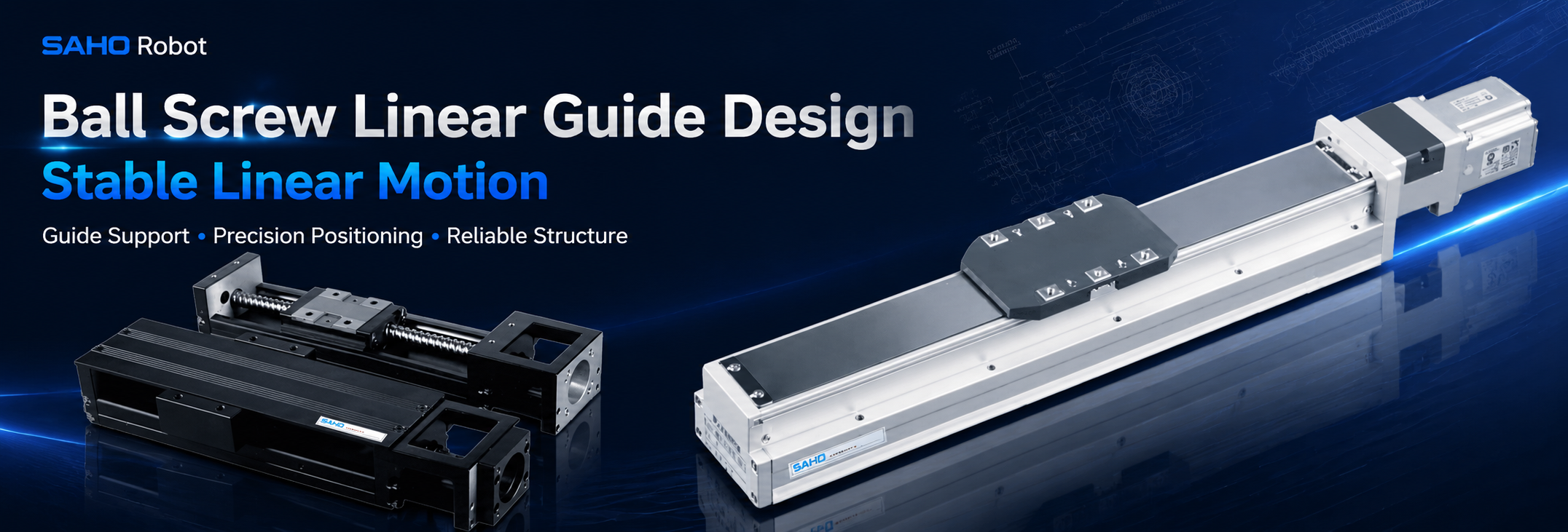
A ball screw linear guide structure decides whether a screw-driven axis can move with stable straightness, controlled rigidity, and repeatable positioning. In industrial automation, the drive screw creates thrust, while the guide rail, carriage, base profile, lubrication path, and dust protection help keep motion reliable under real load. This article explains how guide rail support, carriage stability, moment load, straightness, and maintenance planning affect screw drive module selection for SDH Series screw drive modules and KK Series integrated screw modules.
Unlike a general motion overview, this guide focuses on practical structure decisions. It explains where screw drive modules bring value, how stable guidance supports machine performance, and what selection parameters should be prepared before contacting SAHO for model confirmation.
| Main topic | Screw drive linear module structure for stable linear motion. |
| Key structure points | Guide rail support, carriage stability, moment load, straightness, lubrication, and dust protection. |
| SAHO product direction | SDH Series for built-in screw drive actuator layouts, and KK Series for compact integrated rail and U-shaped body designs. |
| Selection data | Stroke, load, load center distance, speed, acceleration, accuracy, installation direction, motor direction, and working environment. |
Stable Linear Motion Starts from the Mechanical Structure
Stable linear motion is not created by the screw alone. The screw converts motor rotation into linear thrust, but the guide structure controls the moving path. A screw drive module needs a balanced design between the ball screw, guide rail, carriage, bearing support, and base body.
In real equipment, loads rarely sit perfectly above the carriage center. A camera bracket may extend forward. A gripper may create side load. A vertical tool head may add pitching force during acceleration. The guide system must handle more than simple weight.
Repeated production cycles reveal weak structure quickly. A module may look smooth during no-load testing, yet vibration can appear after tooling, cables, workpieces, or upper axes are installed. Guide rail support and carriage stability should be reviewed before the final layout is fixed.
In precision assembly, inspection, dispensing, laser positioning, and small-part transfer, the axis must stop accurately and remain stable. The correct screw drive module should match the motion requirement, the mechanical load, and the working environment.
Key Benefits of a Proper Screw Drive Guide Structure
A well-designed screw drive guide structure gives the moving carriage a predictable travel path. It reduces unwanted tilt, side movement, and vibration during starts and stops. This is important because many automated processes depend on stable tool position, not only nominal stroke length.
Guide support also protects the ball screw from side force. A ball screw works best when it mainly receives axial force along the travel direction. When the guide rail and carriage absorb radial load and moment load, the screw can run with less stress and smoother motion.
Another benefit is repeatability. Repeatability means the carriage returns to the target position again and again under the same working condition. For inspection, dispensing, component placement, and guided tool approach, repeatable motion often matters more than one-time no-load accuracy.
A stable guide structure can also reduce settling time. After the axis stops, the tool should become stable quickly. Stronger carriage support can improve both process quality and cycle rhythm.
| Benefit | Practical value | Structure factor |
| Stable carriage travel | The moving table follows a controlled path during repeated positioning. | Rail support, base straightness, and carriage rigidity. |
| Reduced vibration | The tool settles faster after acceleration and braking. | Moment load control, preload, and mechanical stiffness. |
| Better repeatability | The same position can be reached with less variation over many cycles. | Screw lead, guide accuracy, carriage support, and lubrication. |
| Longer service life | Abnormal stress on the screw, guideway, and bearings is reduced. | Correct load direction, dust protection, and grease maintenance. |
Guide Rail Support: The Foundation of Straight Linear Travel
Guide rail support determines how the moving load transfers into the module body. The guide rail carries the carriage and helps resist vertical force, side force, and overturning force. It should not be treated as a small accessory around the screw.
In a screw drive module, the ball screw provides thrust along the axis, while the guide rail controls direction. If these two lines do not work together, the carriage may feel tight in one area and loose in another area. Over time, this can increase wear and reduce motion smoothness.
The base profile also affects rail straightness. A guide rail mounted on a weak or twisted base cannot maintain a stable path. The module body, mounting surface, and machine frame should support the expected precision requirement.
For medium-stroke automation axes, this support becomes more important. A longer stroke gives the carriage more distance to reveal straightness error. Guide rail support should be checked together with stroke, load, and installation direction.
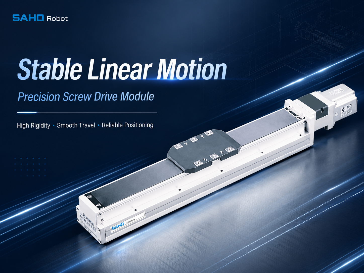
SDH Series screw drive module with built-in actuator structure for stable guided motion.
Carriage Stability: The Contact Point Between Tooling and Motion
Carriage stability decides how well the module handles real tooling. A fixture, sensor, light source, dispensing valve, or small gripper usually mounts on the moving carriage. The carriage must support both the weight and the working force from the tool.
A larger contact area can improve tool support, but a larger carriage is not always the correct answer. The best structure depends on load weight, center of gravity, offset distance, acceleration, installation angle, and process tolerance.
A light camera with a long bracket may create a strong moment load. In contrast, a heavier fixture mounted close to the carriage center may remain easier to support. The location of the load matters as much as the weight itself.
Carriage stability affects process quality directly. A small amount of tilt may change camera focus distance, nozzle height, or tool position. Stable carriage design supports both motion accuracy and production consistency.
Useful carriage stability checks
Calculate the complete moving mass, including fixtures, cables, brackets, sensors, and workpieces.
Measure the distance between the load center and the carriage centerline.
Review acceleration, deceleration, stop time, and vibration requirements.
Confirm whether the module will be horizontal, vertical, side-mounted, or inverted.
Moment Load: A Main Reason for Unstable Screw Drive Motion
Moment load is a turning force created by an offset load. A tool creates more stress when it sits farther from the guide support. A compact tooling layout can sometimes improve stability more effectively than simply selecting a larger motor.
There are three common moment directions. Pitching moment tilts the carriage forward or backward. Yawing moment twists the carriage left or right. Rolling moment rotates the carriage around the travel direction.
In actual machines, these forces often appear together. An offset Z-axis mounted on an X-axis can create pitching during acceleration and rolling under side load. Model selection should consider combined loading, not only catalog payload.
Moment load also influences service life. High overturning stress increases contact pressure inside the guideway. Over time, this may create noise, uneven wear, higher running resistance, and reduced repeatability.
| Moment type | Typical source | Possible effect |
| Pitching | Tool head extends forward or backward from the carriage. | Position shift during acceleration or braking. |
| Yawing | Side force from grippers, cables, workpieces, or external tooling. | Side drift, vibration, and uneven guide loading. |
| Rolling | Load sits above, below, or beside the guide center. | Carriage tilt and shorter guide life. |
Straightness and Alignment: Small Errors Can Become Process Problems
Straightness means the carriage follows a controlled line during travel. Although the motor may reach the target position, poor straightness can still create process variation. Straightness should be considered when the axis carries inspection tools, dispensing nozzles, laser heads, or positioning fixtures.
A camera inspection station may require a constant distance from the inspected surface. A dispensing axis needs a stable path to keep bead width and placement consistent. Guide rail support and base alignment can affect final quality.
Screw alignment matters as well. The screw, nut, bearing support, and guide carriage should move without fighting each other. When alignment is poor, friction rises and the axis may show noise, heat, or uneven motion.
The machine mounting plate can also change the final result. A precise module can twist when mounted on a weak or uneven surface. Mounting flatness, bolt sequence, and support points should match the required motion quality.
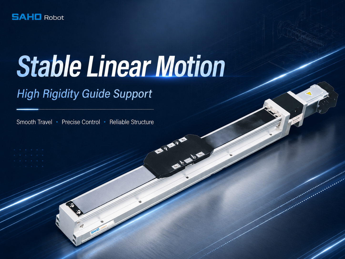
SDH Series structure supports stable carriage travel for screw-driven automation axes.
Lubrication: A Simple Condition That Protects Long-Term Stability
Lubrication keeps the ball screw and guideway running smoothly. A proper grease film reduces friction, helps protect rolling contact surfaces, and supports stable motion over repeated cycles. Lubrication should be part of the design discussion, not only a maintenance note.
Grease access can become difficult after the module enters a compact machine. Guards, brackets, frames, and upper axes may block service points. The mechanical layout should leave enough space for inspection and regular lubrication.
Operating condition changes the maintenance interval. High load, fast cycling, short repetitive strokes, dust exposure, or vertical installation can increase maintenance needs. The grease plan should match duty cycle and environment.
Lubrication problems often appear gradually. Noise, vibration, higher motor current, or unstable stopping can signal changing friction. Scheduled checks help keep the axis stable before obvious failure occurs.
Maintenance items that support smooth travel
Keep guideways clean and remove particles near the carriage path.
Apply the recommended grease type at the correct service interval.
Inspect covers, seals, fasteners, sensors, and cable routes.
Record abnormal sound, vibration, temperature, and motor current changes.
Dust Protection: Keeping the Screw and Guideway Clean
Dust protection has a direct effect on motion stability. Fine particles can mix with grease and create abrasive wear inside the guideway or screw area. A protected structure helps maintain smoother motion for a longer service period.
In production environments, dust does not always look severe at first. Plastic particles, packaging debris, powder, cutting residue, or general plant dust can collect near moving parts. Over time, this buildup can increase friction and reduce positioning consistency.
Covered screw structures and clean carriage paths deserve attention. A cover cannot replace maintenance, but it reduces direct contamination. It can also improve machine safety and make the axis easier to integrate into enclosed equipment.
Dust protection should match the real installation direction. A horizontal axis, vertical axis, side-mounted axis, and inverted axis may collect particles in different areas. The protection plan should be reviewed together with machine layout.
Applications for Stable Screw Drive Linear Modules
Screw drive linear modules are suitable when controlled positioning, rigidity, compact structure, and repeatable movement are important. They fit short-to-medium stroke applications where stable stopping matters more than very long high-speed travel.
In electronic component assembly, an axis may carry a small gripper, tray, camera, or fixture. Because components are small, slight carriage movement can affect placement quality. Guide rigidity and repeatability are important.
For inspection systems, stable linear travel helps maintain camera focus and measuring distance. Smooth stopping helps reduce image blur and alignment errors. A rigid screw-driven guide module can support repeatable inspection stations.
In dispensing and coating processes, nozzle position must stay consistent. A weak carriage can shift under acceleration or hose drag. Moment load control and cable route planning become important selection points.
For laser marking, small part handling, fixture indexing, and precision positioning, a stable screw axis can provide controlled linear travel. The module can simplify installation because the screw, guide, and carriage are already combined into one mechanical unit.
In medical and laboratory automation, compact size and stable motion help move trays, samples, sensors, and small tooling. Noise, cleanliness, lubrication access, and smooth travel should also be considered during selection.
| Application | Why stable guidance matters | Recommended product direction |
| Inspection equipment | Camera distance and stop stability affect image quality. | SDH Series or KK Series depending on space and load. |
| Dispensing systems | Nozzle path consistency affects glue, coating, and bead quality. | SDH Series for built-in screw drive structure. |
| Precision assembly | Repeatable positioning supports placement and tool approach quality. | KK Series for compact high-rigidity layouts. |
| Laboratory automation | Stable movement supports sample handling and sensor positioning. | KK Series or compact SDH configuration. |
For press-related applications, SDH or KK can support guided positioning, fixture movement, or tool approach. When the main process requires direct pushing, pulling, lifting, or controlled electric-actuator movement, the SEH Series electric linear actuator should also be reviewed.
SDH Series: Built-In Screw Drive Actuator for Stable Automation Motion
The SDH Series is suitable when a built-in actuator structure can simplify machine integration. The module combines screw drive motion, guide support, carriage movement, and practical protection into a linear axis. It can reduce the work needed to design separate rail, screw, bearing, and cover assemblies.
SDH Series modules fit equipment that requires stable positioning and a clean mechanical layout. The built-in form helps reduce direct exposure to the moving mechanism, while the carriage provides a mounting surface for fixtures, tools, sensors, or small handling devices.
For inspection, dispensing, electronic assembly, and general precision positioning, SDH can support repeatable movement across a controlled stroke. The final model should still be selected by load, stroke, speed, accuracy, moment condition, and installation direction.
SDH Series is useful when equipment design needs a balance between protection, rigidity, and installation efficiency. It is not a long-stroke belt axis. It is a screw-driven module direction for applications where accuracy and stable guidance matter.
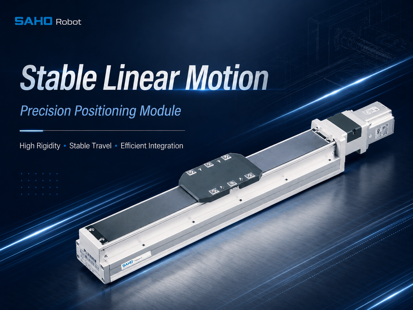
SDH Series built-in screw drive actuator for stable positioning and practical module layouts.
KK Series: Integrated Guide Rail and U-Shaped Body for Compact Rigidity
The KK Series supports compact screw-driven motion where rigidity and installation efficiency are important. Its integrated structure combines ball screw drive, guide rail support, and a U-shaped body design. This can help reduce space while maintaining stable guidance.
This structure is useful for smaller automation machines, compact inspection stations, fixture positioning, and auxiliary axes. In many cases, limited installation space makes separate screw and rail assembly difficult. An integrated module can make the layout cleaner and easier to control.
The U-shaped body supports guide alignment and module rigidity. This helps the carriage resist motion variation during repeated operation. For compact equipment, that stability can improve assembly accuracy, measurement consistency, and tool positioning.
KK Series selection should still follow application data. Stroke, load, screw lead, motor direction, accuracy requirement, and environmental protection should be reviewed before final confirmation.
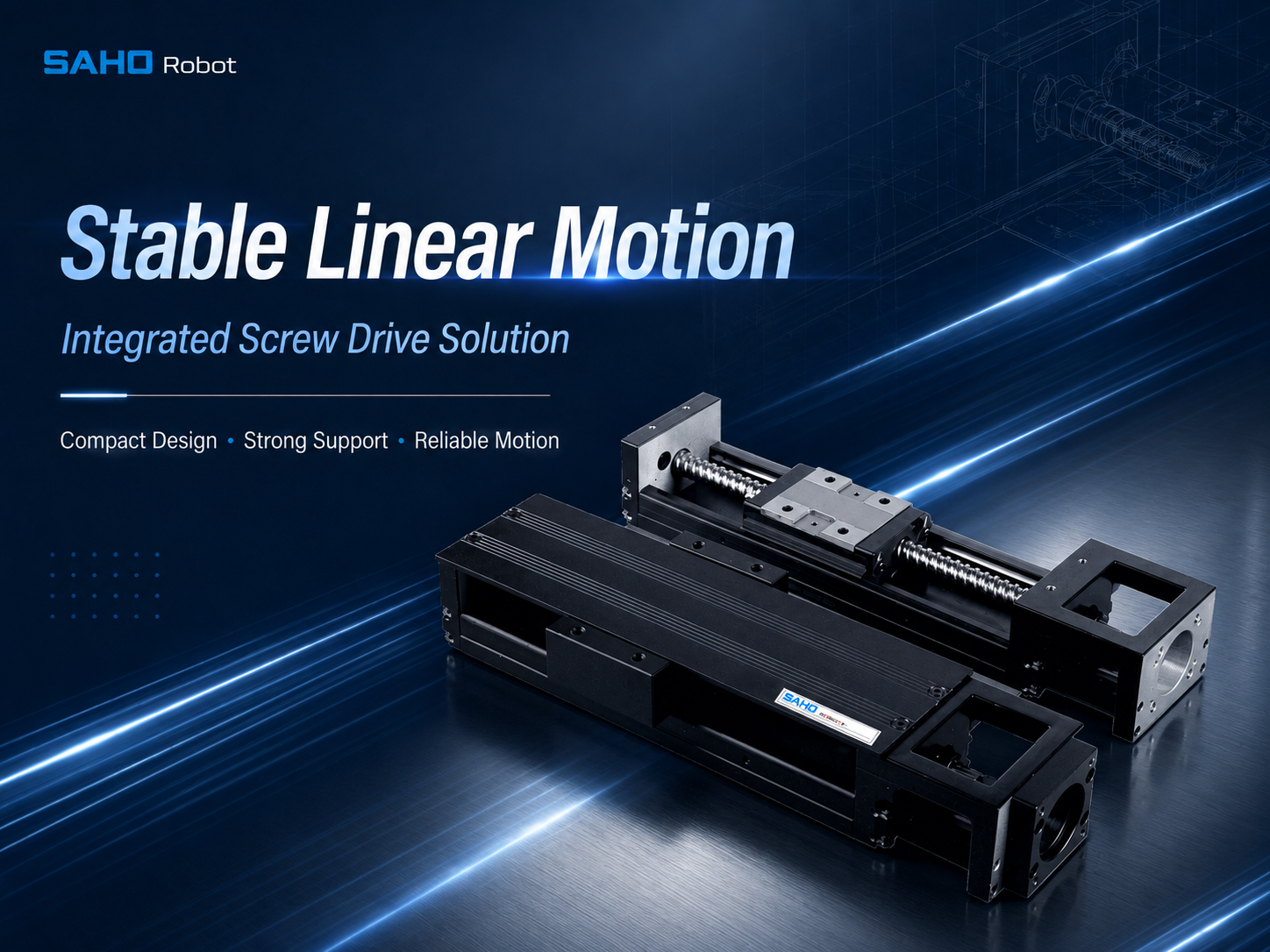
KK Series integrated guide rail and U-shaped body design for compact screw-driven axes.
SDH Series vs KK Series: How to Choose the Right Direction
SDH Series and KK Series both belong to screw drive module selection, but they answer different layout needs. SDH is helpful when a built-in actuator style and practical protection are preferred. KK is helpful when compact integrated rail support and U-shaped body rigidity are priorities.
Application size changes the decision. A machine with more open space may use SDH to gain a practical built-in axis. A smaller machine may use KK to save space and simplify integration. Structure and installation space should be reviewed together.
Load condition can also guide selection. A wider tooling plate, longer bracket, or higher moment load may require a different carriage and rail support. Drawings and load center data are valuable during model review.
| Selection point | SDH Series direction | KK Series direction |
| Machine layout | Suitable for built-in actuator layouts with practical screw drive protection. | Suitable for compact axes with integrated guide rail support. |
| Space condition | Useful when the machine has enough room for a built-in module body. | Useful when a compact U-shaped body helps save installation space. |
| Typical tasks | Inspection, dispensing, positioning, and medium-duty precision automation. | Compact transfer, small assembly, inspection, and auxiliary positioning axes. |
| Main benefit | Built-in actuator form with stable guided movement and practical integration. | Compact high-rigidity structure with integrated rail and screw design. |
Selection Tips: Parameters to Prepare Before Model Confirmation
A reliable selection starts with complete application data. The required stroke should be defined clearly. This includes effective travel, end clearance, sensor space, and any overtravel allowance.
Load data should include more than the workpiece. Fixtures, brackets, grippers, cables, sensors, moving plates, and any upper axis should be included. The load center distance should also be measured because it affects moment load.
Speed and acceleration also matter. A moderate top speed with harsh acceleration can create more vibration than a smoother motion profile. Cycle time, acceleration time, and stop stability should be discussed together.
Accuracy should be described in process terms. Some systems need repeatable stops at fixed positions. Others need smooth travel for scanning or dispensing. The required repeatability, straightness, and motion smoothness should be stated clearly.
Installation direction changes the mechanical load. A horizontal axis mainly carries payload and dynamic force. A vertical axis also needs gravity holding, brake motor consideration, and power-off safety review.
The working environment should be shared as well. Dust, humidity, oil mist, temperature, cleaning method, and particle exposure can change lubrication and protection needs. For wider automation background, the Association for Advancing Automation provides useful industry context on automation technologies and application trends.
| Parameter | What to provide | Why it matters |
| Stroke | Effective travel, end clearance, and installation space. | It affects screw length, module size, speed limit, and rigidity. |
| Load | Total moving mass and load center distance. | It decides carriage support and moment load requirement. |
| Speed | Target speed, acceleration, cycle time, and duty cycle. | It affects screw lead, motor sizing, heat, and vibration. |
| Accuracy | Repeatability, straightness, stop stability, and process tolerance. | It helps match the module structure with the process requirement. |
| Installation direction | Horizontal, vertical, side-mounted, or inverted mounting. | It changes load direction, brake needs, and service access. |
| Environment | Dust, oil mist, temperature, humidity, and cleaning method. | It affects protection, lubrication, and long-term reliability. |
Recommended Selection Route for SAHO Screw Drive Modules
A clear selection route can reduce mistakes. Start by defining the process result that the motion axis must support. This may be accurate inspection, stable dispensing, repeatable transfer, smooth positioning, or compact tooling movement.
Convert the process need into mechanical data. Stroke, payload, tool offset, speed, acceleration, and installation direction should be listed. The working environment should also be described because dust and maintenance access can affect service life.
Then compare the module direction. SDH Series can suit built-in screw drive actuator layouts. KK Series can suit compact integrated guide rail layouts. The decision should follow both machine space and guide rigidity needs.
Send the data to SAHO for model review. A drawing or simple sketch can help define the load center and mounting direction. The final recommendation can be more accurate than selecting by catalog size alone.
| Step 1 | Define the process task: inspection, dispensing, assembly, transfer, positioning, or vertical movement. |
| Step 2 | Prepare stroke, load, speed, acceleration, accuracy, installation direction, and working environment. |
| Step 3 | Choose the structure direction: SDH for built-in actuator layouts, or KK for compact integrated rail layouts. |
| Step 4 | Confirm model, motor direction, sensor position, cable route, lubrication access, and dust protection with SAHO. |
Common Design Mistakes to Avoid
One common mistake is selecting only by payload weight. Weight is important, but it does not show where the load is located. The load center distance should always be checked.
Another mistake is ignoring moment load. A long bracket, side-mounted gripper, or upper-axis assembly can create strong overturning force. Carriage support and guide rigidity should match the actual tooling layout.
Some machine designs focus only on top speed. Stable stopping, low vibration, and repeatable positioning often decide the real process result. The motion profile should match the process requirement, not just the fastest possible travel.
Mounting flatness is also easy to overlook. A strong module can still twist when installed on an uneven plate. The machine base should be prepared carefully and fasteners should be tightened in a controlled sequence.
Maintenance access should not be left until the end. Grease points, cover removal space, sensors, and cable chains must remain reachable after guarding and tooling are installed. Otherwise, long-term motion stability may decline even when the original selection was correct.
Related SAHO Screw Drive Products
For this topic, the relevant SAHO product direction is screw drive linear module selection. SDH Series and KK Series both support stable guided linear motion, but each one fits a different mechanical layout. The choice should follow machine space, required rigidity, and process load.
The following table keeps the selection route simple. It does not mix belt drive modules or linear motor modules into this screw drive article.
| SAHO series | Structure | Suitable scenarios | Action |
| SDH Series | Built-in screw drive actuator with practical module structure and carriage support. | Inspection, dispensing, positioning, and precision automation layouts. | View SDH Series |
| KK Series | Integrated ball screw, guide rail, and U-shaped body structure. | Compact machines, small transfer axes, inspection stations, and auxiliary positioning. | View KK Series |
FAQ
Why does linear guide structure matter in screw drive modules?
Linear guide structure matters because the guide carries radial load, side force, and moment load while the screw provides thrust. The guide controls carriage alignment, straightness, rigidity, and stable stopping. A precise screw cannot deliver reliable motion alone if the guide structure is not suitable.
How does moment load affect stability?
Moment load creates a turning force on the carriage. An offset camera, gripper, nozzle, or mounted axis can pull the carriage away from the guide center. Excessive moment load can cause tilt, vibration, uneven guide wear, and reduced repeatability.
What maintenance helps keep motion stable?
Regular lubrication, clean guideways, dust cover inspection, bolt checks, and abnormal noise monitoring help keep motion stable. Grease interval should match load, speed, duty cycle, and working environment. A planned maintenance route is especially important inside compact machines.
When is SDH Series suitable?
SDH Series is suitable when a built-in screw drive actuator layout, practical module structure, and stable carriage support are required. It fits equipment that needs controlled positioning, clean mechanical integration, and practical fixture mounting.
When is KK Series suitable?
KK Series is suitable when compact installation and integrated rigidity are priorities. Its ball screw, guide rail, and U-shaped body structure support small automation axes where space is limited but stable guidance remains important.
Conclusion and Actionable Selection Advice
A stable screw drive axis depends on more than motor power or screw lead. Guide rail support, carriage rigidity, moment load, straightness, lubrication, and dust protection all affect final performance. A ball screw linear guide design should be selected by complete application data and real machine layout conditions.
For a practical selection route, three actions are recommended:
Define stroke, load, speed, acceleration, accuracy, installation direction, and environmental conditions before choosing a model.
Check load center distance, moment load, mounting flatness, lubrication access, and dust protection during mechanical layout.
Compare SDH Series and KK Series with SAHO based on the actual tooling layout, motion profile, and space restriction.
Need help selecting a screw drive linear module? Send stroke, load, speed, accuracy, acceleration, installation direction, motor direction, tooling layout, and working environment details to SAHO. The engineering team can review the data and recommend a suitable SDH Series or KK Series structure for stable linear motion. Contact SAHO for Selection Support |







-
-
 English
 -
 Français
 -
 Deutschland
 -
 Italia
 -
 Polska
 -
 España
 -
 Русский язык
 -
 日語
日語 -
 한국
한국 -
 Türkiye
 -
 português
 -
 بالعربيةês
 -
 Tiếng Việt
 -
 คนไทย
คนไทย -
 简体中文
简体中文 -
繁體中文
-