

Date:2026-07-20 Click:366
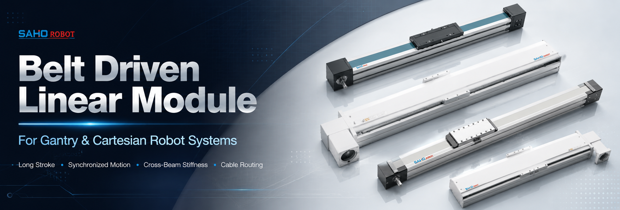
A Belt Driven Linear Module gives gantry and Cartesian robot systems a practical way to build long-stroke motion, high-speed transfer, and stable multi-axis handling. In a real machine, the main axis is not only a travel part. It also carries a cross beam, cable chain, end tooling, sensors, and sometimes another complete axis. The module choice affects stroke planning, frame stiffness, synchronized motion, service access, and final production rhythm.
This article focuses on SAHO belt-drive linear modules for gantry axis and Cartesian robot layouts. The key topics include long-stroke X-axis movement, dual-axis synchronization, cross-beam stiffness, cable routing, motor matching, model selection, and engineering data preparation. It explains how TA Series, TR Series, and MTG Series can be matched with different automation structures. JTG and STM are included only as related belt-drive options for special or general environments, so the article stays focused on gantry and Cartesian robot selection.
Why Belt-Drive Modules Are Useful in Gantry Systems
Gantry systems often need long travel in the main movement direction. A packaging line, battery line, electronics line, photovoltaic line, or panel handling system may need one axis to move across several stations. A belt-drive module can support long-stroke motion with a clear mechanical structure.
Cycle time also matters. A long axis that moves slowly can limit the complete production process. Belt-drive modules are often selected when long travel, repeatable positioning, and fast transfer are more important than very high thrust at short stroke.
A gantry robot does not work as one isolated part. The main axis may carry a cross beam, the cross beam may carry a Y-axis, and the Y-axis may carry a Z-axis or end effector. The selected module must work with the frame, beam, motor, controller, and cable system.
Modular construction helps reduce design work. A ready belt module already combines the profile, guide system, belt path, carriage, end blocks, and motor mounting area. The module alone still cannot solve every motion issue. Cross-beam deflection, tool offset, cable chain drag, mounting flatness, and synchronization quality should be reviewed as part of the full gantry structure.
| Gantry Requirement | Why a Belt Module Helps | Engineering Check |
| Long X-axis stroke | Supports wide working areas and multi-station transfer. | Confirm total stroke, working stroke, end clearance, and support length. |
| Fast transfer cycle | Helps reduce travel time between process positions. | Review acceleration, settling time, moving mass, and motor sizing. |
| Cross-beam support | Provides a ready linear axis for bridge or cross-axis mounting. | Check beam stiffness, tool offset, carriage moment, and axis spacing. |
| Synchronized dual axes | Allows wide gantry structures to move as one frame. | Check homing method, gantry squaring, control logic, and alarm protection. |
Gantry Axis Layout: X, Y, Z, and Cross-Beam Planning
In a typical gantry robot, the X-axis is the longest axis. It often carries the bridge or cross beam across the main work envelope. The X-axis normally sets the machine footprint, travel range, and many parts of the cycle time.
The Y-axis moves across the beam. This axis may carry a gripper, suction head, camera, dispenser, label head, test probe, or small Z-axis. The Y-axis should be selected together with beam stiffness and the moving mass on the carriage.
The Z-axis usually handles vertical approach, lifting, tool positioning, or light process movement. If the main process requires direct pressing, pushing, pulling, or controlled actuator force, a dedicated vertical axis or electric actuator solution should be reviewed separately instead of assuming a belt-driven gantry axis can handle every process force.
A single-side gantry uses one X-axis to carry the beam from one side. This layout can work for compact machines, light tools, and short beam spans. The offset load can create twisting, so moment load and carriage support must be checked carefully.
A dual-X gantry uses two parallel axes to carry the bridge together. This layout is better for wider spans and heavier cross beams. It also requires accurate alignment and synchronized motion because a small position mismatch can force the frame out of square.
Axis spacing affects stiffness. Wider spacing between the two X-axes can improve beam support, but it increases the need for careful frame machining and assembly. The base frame should be rigid enough before the modules are installed. For industry context, the A3 Association for Advancing Automation covers automation, robotics, vision, motion control, and related manufacturing technologies.
Long-Stroke X-Axis Design for Transfer and Handling
Long-stroke motion is the main reason many gantry systems use belt-drive modules. A long X-axis can connect loading, process, inspection, and unloading stations in one straight path. This can reduce extra handling points and keep the machine layout more organized.
The working stroke and the total module length are not the same. The working stroke covers the useful process movement. Total length must also include end blocks, carriage length, sensor space, cable chain return area, motor side clearance, and maintenance access.
Acceleration matters as much as maximum speed. A long axis may have enough distance to reach high speed, but a short station-to-station move may not. Real cycle time should be calculated with acceleration, deceleration, dwell time, and settling time.
For long travel, the machine base should keep the module straight and flat. If the base twists or bends, the carriage may carry extra load from the frame instead of the application. Mounting surface, bolt points, and support structure should be reviewed before final assembly.
The TA Series is a strong starting point for long X-axis transfer when travel length, speed, and profile strength are important. For special environments or more enclosed general-environment layouts, JTG and STM can be reviewed later as related belt-drive options, but they should not replace the main TA / TR / MTG selection logic of this article.
Synchronized Motion in Dual-Axis Gantry Systems
Synchronized motion becomes important when two parallel X-axes support one bridge. Both sides must start, accelerate, move, slow down, and stop together. If one side moves slightly ahead of the other side, the bridge may rack.
Racking increases guide stress and may create noise, vibration, or positioning error. In severe cases, it can shorten service life or cause alarm stops. Dual-X gantries need mechanical alignment and control planning from the start.
One common solution uses two servo motors with electronic synchronization. This approach allows independent feedback and drive tuning on each side. The controller must manage home sensors, following error, gantry squaring, and fault response.
Another solution uses mechanical synchronization through a shaft or coupling. This can simplify the control side in some layouts. The shaft, couplings, bearings, and torsional stiffness must still be sized correctly.
Homing accuracy and emergency stop behavior also matter. Dual-axis gantries often use sensors on both sides to square the bridge during machine startup. If one side stops and the other continues, the bridge can twist. Alarm logic, drive enable timing, and brake behavior should be tested before full-speed production.
| Synchronization Item | Reason | Recommended Review |
| Dual home sensors | Helps square the bridge before motion starts. | Check sensor repeatability, bracket rigidity, and wiring path. |
| Servo following error | Shows whether both axes track the motion command properly. | Review drive tuning, payload, acceleration, and alarm limit. |
| Bridge squareness | Reduces guide stress and improves repeatable travel. | Measure parallelism, diagonal distance, and beam connection points. |
| Emergency stop logic | Protects the frame from one-sided motion. | Test drive disable timing, brake response, and restart process. |
Cross-Beam Stiffness and Moment Load Control
Cross-beam stiffness is one of the most important points in a gantry structure. The beam carries the Y-axis, Z-axis, tooling, cables, hoses, and sometimes process force. Its bending and twisting directly affect tool position.
For wide spans, vertical deflection can change tool height. This may affect inspection, dispensing, loading, or part placement. Beam torsion can also change tool angle, especially when the payload hangs below the beam centerline.
Moment load is another key issue. A tool mounted far from the carriage face acts like a lever, so the guide and carriage receive higher load than the simple payload weight suggests.
Payload should include the moving plate, brackets, tool head, product, cable chain section, hoses, and fittings. The center of gravity should be measured in three directions when possible. This gives a more accurate basis for module and beam selection.
Dynamic movement also needs review. When the gantry accelerates, the effective load increases. Acceleration, jerk setting, tool offset, beam natural frequency, and settling time should be considered together.
| Stiffness Check | What It Affects | Useful Design Action |
| Beam bending | Tool height, camera focus, part pickup level, and dispensing gap. | Increase beam section, shorten unsupported span, or reduce acceleration. |
| Beam torsion | Tool angle, placement quality, and edge alignment. | Use stronger beam geometry and balanced mounting plates. |
| Carriage moment | Guide life, vibration, and repeatability. | Check tool offset, moving mass, and carriage support length. |
| Frame rigidity | Parallelism, smooth travel, and long-term alignment. | Use a stable base frame and verify mounting surface flatness. |
Cartesian Robot Layouts and Axis Matching
A Cartesian robot usually combines two or three straight axes into an X-Y, X-Z, or X-Y-Z structure. This layout is common in handling, loading, inspection, dispensing, testing, marking, and assembly equipment. Because each axis carries the next one, moving mass increases from the tool side back to the main axis.
For example, the X-axis may carry the Y-axis, the Z-axis, all tooling, and part weight. The X-axis needs a stronger load calculation than the tool axis. The Y-axis may need enough stiffness to control offset tooling and process force.
In compact Cartesian layouts, the TR Series can be used for cross-axis movement and standard belt module integration. Its Euro standard structure helps with machine layout, mounting planning, and repeatable axis design. TR is especially relevant for Y-axis, medium-stroke transfer, pick-and-place, inspection, and dispensing structures.
For clean room, electronics, TFT-LCD, medical equipment, and precision automation layouts, MTG Series is another SAHO belt-drive option. It remains a linear module product, not a linear motor product, and it can support XY, XYZ, and gantry-style robot structures.
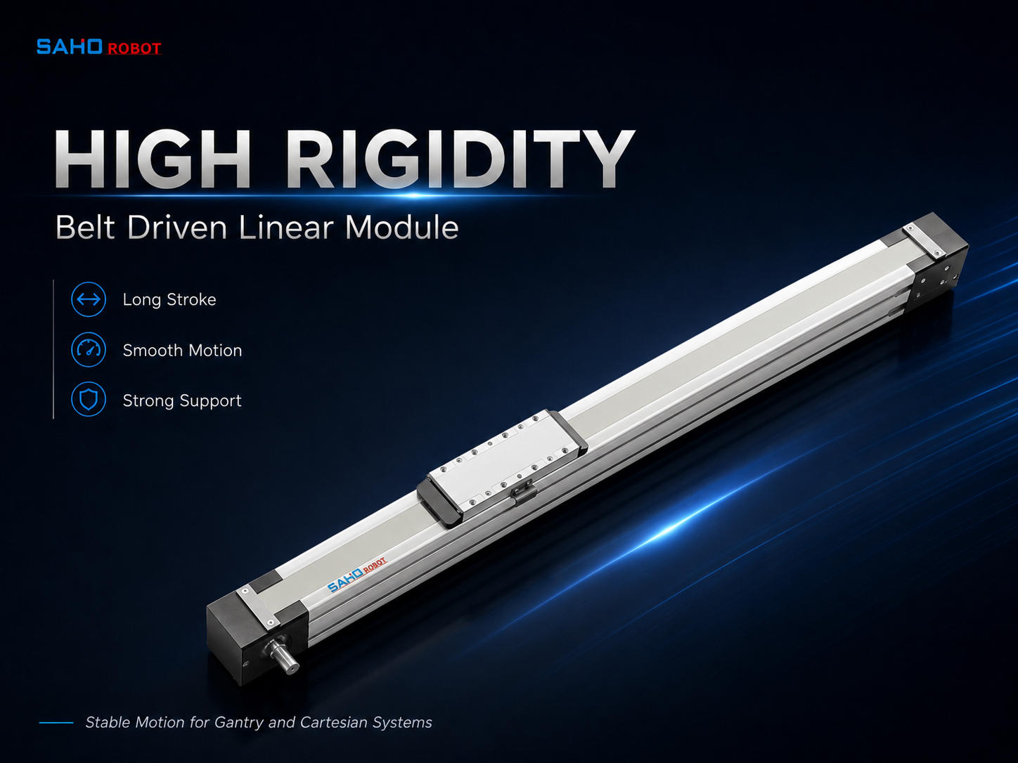
MTG60 can be reviewed for clean-room-oriented Cartesian robot axes, electronics handling, inspection equipment, and compact multi-axis automation structures.
Cable Routing for Moving Gantry and Multi-Axis Systems
Cable routing is often underestimated in gantry design. A moving bridge may carry servo cables, encoder cables, sensor cables, air tubes, vacuum hoses, communication cables, lights, and camera lines. The cable chain should be planned with the module layout, not after the frame is finished.
The cable chain must fit the stroke and bend radius. If the bend radius is too small, cable life may drop. The chain should also avoid collision with guards, brackets, product fixtures, or nearby machines.
Moving cable weight should be included in the payload calculation. A long cable chain on a gantry bridge can add meaningful mass. This can change acceleration, motor sizing, and vibration behavior.
Routing direction affects service access. A side-mounted cable chain may keep the top surface clear, while an overhead route may protect hoses better in some machines. Chain direction should follow the machine guard, operator access, and maintenance plan.
Signal stability also needs proper wiring practice. Servo power cables and feedback cables should follow suitable separation, shielding, grounding, and connector planning. Full-stroke testing at low speed can reveal chain drag, connector strain, and collision before high-speed operation starts.
Applications That Fit This Motion Concept
In packaging automation, gantry modules can move cartons, trays, pouches, bags, bottles, and finished products between stations. The long X-axis covers the main transfer path, while the cross-axis or Z-axis handles pickup, placement, or inspection.
In lithium battery production, gantry systems can support cell handling, tray loading, module transfer, inspection, stacking, and station-to-station movement. These systems often need long stroke, stable cycle time, and clear access for maintenance.
In electronics assembly, Cartesian robots often carry cameras, dispensers, screwdriving heads, test probes, and small grippers. The payload may be moderate, but repeatable movement and low vibration are important. Compact routing for cables and air tubes helps keep the machine clean.
In TFT-LCD and panel handling, the working area can be wide. A gantry may move a suction tool, camera, or measuring head across a large surface. Cross-beam stiffness and tool height stability become essential.
In photovoltaic equipment, long-axis movement may support wafer handling, panel positioning, inspection, or transfer between stations. The moving tool can be wide and sensitive to vibration, so the frame, beam, module, and cable chain must work as one system.
In automotive, white goods, medical, and precision equipment automation, Cartesian systems can move parts, apply adhesive, place clips, handle fixtures, or support inspection. These lines may run for long hours, so maintenance access, belt tension checks, guide lubrication, and predictable repeatability should be included in the early design.
TA, TR, and Related Belt-Drive Module Selection Ideas
Model selection should begin with the machine structure. A long X-axis with a heavy bridge is different from a compact Y-axis on a small Cartesian robot. The series choice should follow stroke, load, profile stiffness, installation direction, and space limits.
The TA Series is generally suitable for long-stroke X-axis movement and heavier transfer layouts. It can support gantry structures where travel length, speed, and profile strength are important. It is also useful when the main axis carries a bridge or a larger moving assembly.
The TR Series is suitable for Euro standard belt module layouts and cross-axis integration. It can support Cartesian robot structures where module size, mounting style, and clean installation matter. TR models often fit Y-axis, medium-stroke transfer, and compact handling structures.
MTG should be reviewed when clean-room-oriented belt-driven motion is required. JTG and STM can be reviewed as related belt-drive options according to environment, protection needs, machine style, and integration space. This keeps the article within SAHO linear module products and avoids mixing in linear motor series.
| SAHO Series | Best-Fit Role | Suitable Project Type | Selection Notes |
| TA Series | Long-stroke X-axis and heavier transfer axis. | Gantry transfer, packaging, battery, panel, and automation lines. | Check stroke, moving mass, beam load, acceleration, and frame support. |
| TR Series | Cross-axis, Y-axis, and standard Cartesian robot axis. | Pick-and-place, inspection, dispensing, test, and handling systems. | Check carriage load, axis mounting, cable routing, and tool offset. |
| MTG Series | Clean-room-oriented and precision belt-drive axis. | Electronics, TFT-LCD, medical equipment, and clean room automation. | Check cleanliness needs, load, speed, and multi-axis layout. |
| JTG Series | Related belt-drive option for special environments. | Protected transfer axis layouts and special automation conditions. | Use as a related option after the environment is confirmed. |
| STM Series | Related general-environment belt-drive actuator. | Handling, transfer, machine loading, and general automation lines. | Review enclosure style, motor side, frame space, and service access. |
Selection Data to Prepare Before Model Matching
A reliable selection process starts with complete application data. Stroke and payload are important, but they are not enough. The moving structure, acceleration, duty cycle, installation direction, and cable chain mass also affect the final choice.
Define working stroke and total stroke separately. Working stroke describes useful process movement. Total stroke should include approach distance, safety clearance, sensor position, end clearance, and service movement.
Calculate moving mass carefully. This should include the carriage plate, brackets, tooling, gripper, product, cable chain, hoses, and moving sensors. The center of gravity should be included because an offset load changes the moment on the carriage.
Check speed and acceleration separately. Maximum speed sounds important, but acceleration often controls short moves. A motion profile with acceleration, constant speed, deceleration, dwell time, and settling time is more useful than speed alone.
Define accuracy and repeatability in process terms. A camera inspection axis may need low vibration after stopping. A pick-and-place axis may need stable pickup position. A dispensing axis may need smooth path control instead of only point repeatability.
Installation direction and environment should also be described. Horizontal mounting is common for long X-axis and Y-axis movement. Side mounting, wall mounting, inverted mounting, and vertical movement change the load direction and safety requirements. Dust, oil mist, temperature change, chips, cleaning fluid, static electricity, and humidity can affect module life.
| Selection Item | Data Needed | Why It Matters |
| Stroke | Working travel, full travel, end clearance, and station spacing. | Prevents collision and supports correct module length. |
| Load | Moving mass, product weight, tool weight, and center of gravity. | Affects guide load, belt force, motor torque, and vibration. |
| Speed | Maximum speed, acceleration, cycle time, and dwell time. | Balances output rate with stability and motor capacity. |
| Accuracy | Repeatability target, process tolerance, and settling time. | Connects axis performance with real production results. |
| Installation | Horizontal, side, wall, inverted, or vertical mounting. | Changes moment load, safety checks, and service access. |
| Cable routing | Cable chain direction, hose count, bend radius, and side space. | Reduces drag, collision risk, and future maintenance problems. |
Motor, Drive, Sensor, and Control Matching
A belt module needs a suitable motor and drive to perform well. The motor should match moving mass, acceleration, belt force, friction, and duty cycle. Otherwise, the axis may move at low speed but struggle during fast acceleration.
A reducer may help when more torque is needed, but reducer ratio affects speed, inertia, and response. Motor and reducer matching should follow the real motion profile instead of a simple speed target.
For Cartesian robots, coordinated motion can be important. The X-axis and Y-axis may move together while the Z-axis approaches at a controlled point. The controller should manage timing, acceleration, path planning, and process signals reliably.
Sensors also need early planning. Home sensors define the reference point. Limit sensors protect stroke ends. Additional sensors may confirm station position, tool status, or safety condition. Sensor brackets and wiring space should be included in the layout.
Frame, Mounting Surface, and Alignment
A strong module still needs a strong mounting base. If the frame bends, twists, or lacks support, the module cannot maintain smooth travel by itself. The base frame should be designed with enough rigidity for the full stroke and payload.
During assembly, straightness and parallelism should be checked carefully. This is especially important for dual-X gantries. If two axes are not parallel, the bridge may bind and the guides may receive extra stress.
Mounting bolt sequence also matters. Uneven tightening can twist a profile or create local stress. The module should be installed on a prepared surface with bolt tightening controlled in a clear sequence.
After assembly, the gantry should move slowly across the full stroke before speed testing. This helps find tight spots, chain drag, sensor interference, and end clearance problems. Higher speed testing can then start with less risk.
Maintenance and Service Planning
Maintenance access should be planned before the machine is built. Belt tension, guide lubrication, sensor position, pulley condition, and cable chain wear all affect long-term operation. Guards and covers should allow reasonable inspection and adjustment.
Belt condition should be checked during scheduled maintenance. Unusual noise, uneven tracking, frayed belt edges, or changing tension may indicate alignment or load problems. Belt inspection should be connected with vibration and cycle-time review.
Guide lubrication should match operating hours and environment. Clean lubrication supports smooth motion and helps protect guide life. Too much grease may attract dust in some production areas, so the maintenance method should match the actual environment.
Cable chains also need inspection. Moving cables can wear at bend points or connectors. Strain relief, bend radius, and cable separation should remain visible enough for service.
Common Design Mistakes to Avoid
One common mistake is selecting the axis only by payload. Payload does not show acceleration force, tool offset, cable chain mass, or cross-beam deflection. A complete calculation should include moving mass and moment load.
Another mistake is ignoring the beam. A strong linear module cannot fix a weak bridge. A light beam may vibrate after the axis stops, increasing settling time and reducing process stability.
Cable routing is also often added too late. Late cable planning can create tight bends, blocked access, chain collision, or poor service space. Cable chain layout should appear in the first machine drawing.
Setting acceleration too high can also create problems. Fast movement may look attractive, but a machine only gains output when the tool arrives and settles quickly. A smoother acceleration profile can sometimes create a better real cycle.
A final mistake is treating every axis as the same type of load. The main X-axis, cross Y-axis, and vertical Z-axis have different load directions. Each axis should be selected according to its real duty in the system.
Procurement and Engineering Notes for a Clear Inquiry
A clear inquiry should include basic motion data and a simple layout sketch. The sketch does not need to be complex, but it should show the X-axis, Y-axis, Z-axis, motor side, cable chain side, beam span, and tooling position.
For long X-axis selection, the key data includes total stroke, working stroke, payload, cross-beam weight, maximum speed, acceleration, and expected repeatability. The mounting direction and machine base structure should also be described.
For cross-axis selection, the key data includes moving Y-axis weight, Z-axis weight, tool offset, process force, and cable chain mass. A simple center-of-gravity note can improve model recommendation quality.
For synchronized gantry selection, the key data includes dual-axis spacing, beam width, homing method, drive control plan, and expected squareness requirement. The control method should be noted if two motors will be used.
For maintenance planning, the key data includes operating hours, environment, dust level, oil mist, temperature range, and available service space. This helps decide whether cover, sensor, cable, or lubrication details need extra attention.
Related SAHO Product Pages
| Related Page | Why It Is Relevant | Open Page |
| TA Series | Long-stroke belt-drive modules for heavier transfer and gantry X-axis layouts. | View TA Series |
| TR Series | Euro standard belt modules for Cartesian robot axes and cross-axis integration. | View TR Series |
| MTG Series | Clean-room-oriented belt-drive modules for electronics, medical, TFT-LCD, and multi-axis systems. | View MTG Series |
| JTG Series | Related belt-drive modules for special environments and protected transfer axis layouts. | View JTG Series |
| STM Series | Related general-environment belt-drive actuators for handling, transfer, and machine integration. | View STM Series |
FAQ
Can belt-drive linear modules be used in gantry robots?
Yes. Belt-drive linear modules are suitable for many gantry robot systems, especially long horizontal travel axes and fast transfer paths. Stroke, payload, acceleration, beam stiffness, cable routing, and synchronization should be checked before the final model is selected.
What should be checked for cross-axis stiffness?
Cross-axis stiffness should include beam deflection, torsional stiffness, carriage moment, tool offset, moving Y-axis mass, Z-axis mass, and process force. Acceleration and settling time should also be reviewed because dynamic motion can increase vibration.
When should TA Series be selected?
TA Series is suitable for long-stroke X-axis movement, heavier transfer layouts, and gantry structures that carry a cross beam. It is relevant when travel length, profile strength, speed, and maintenance access are important selection factors.
When should TR Series be selected?
TR Series is suitable for Euro standard belt module layouts, cross-axis movement, and compact Cartesian robot structures. It can be considered for Y-axis movement, medium-stroke handling, inspection, dispensing, and modular machine integration.
When is MTG Series useful?
MTG Series is useful when clean-room-oriented motion, precision automation, electronics handling, medical equipment, TFT-LCD handling, or compact XY and XYZ systems are required. It remains a belt-driven linear module product, not a linear motor product.
How should cable routing be planned for a gantry axis?
Cable routing should be planned at the same time as the axis layout. The cable chain direction, bend radius, hose count, moving cable mass, and available side space should be checked to prevent drag, collision, poor service access, and early cable wear.
Is the highest speed always the best choice?
No. Maximum speed is only one part of the motion profile. In many systems, acceleration, deceleration, dwell time, and settling time decide the real cycle. A stable profile with controlled vibration may perform better than a very high peak speed.
What information helps SAHO recommend the right module?
Useful information includes stroke, load, speed, acceleration, repeatability target, installation direction, beam span, tool offset, moving cable chain mass, working environment, and whether the system uses single-axis or synchronized dual-axis motion.
Conclusion and Practical Selection Advice
A gantry or Cartesian robot system depends on more than one axis. Long stroke, synchronized movement, cross-beam stiffness, cable routing, motor matching, and maintenance access all shape final machine performance. Axis selection should be connected with the complete motion structure, not only the catalog load rating.
For long X-axis transfer, TA Series can support gantry movement and wide working areas. For cross-axis and standard Cartesian layouts, TR Series provides a practical belt-drive module format. MTG, JTG, and STM Series can support related belt-drive module needs in clean room, special environment, and general automation projects.
Before final selection, three practical actions are recommended:
Prepare stroke, load, speed, acceleration, repeatability, installation direction, and environment data.
Check beam span, tool offset, carriage moment, and synchronized motion requirements.
Plan cable chain path, sensor position, motor side, service space, and maintenance access early.
Contact SAHO for Gantry Axis SelectionFor a gantry or Cartesian robot project, SAHO can review stroke, load, speed, accuracy, acceleration, installation direction, beam span, tool offset, cable routing, synchronization requirements, and working environment. Based on this data, TA Series, TR Series, MTG Series, or another suitable belt-drive linear module can be matched to the real machine structure. |







-
-
 English
 -
 Français
 -
 Deutschland
 -
 Italia
 -
 Polska
 -
 España
 -
 Русский язык
 -
 日語
日語 -
 한국
한국 -
 Türkiye
 -
 português
 -
 بالعربيةês
 -
 Tiếng Việt
 -
 คนไทย
คนไทย -
 简体中文
简体中文 -
繁體中文
-