

Date:2026-07-27 Click:262
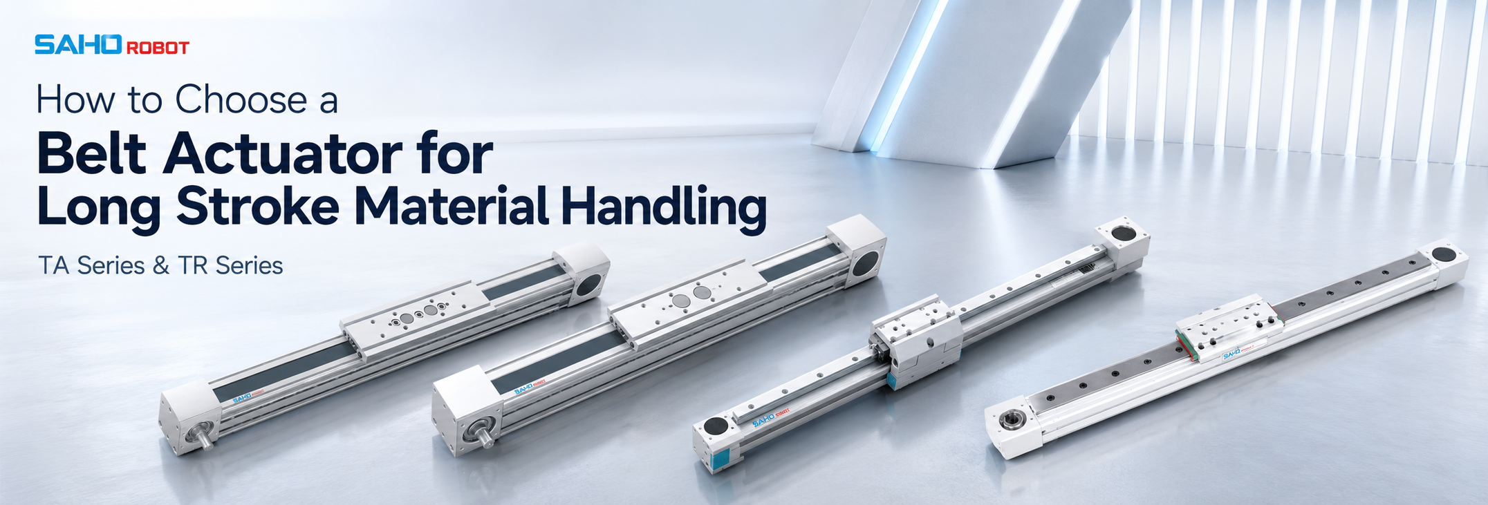
A belt actuator is often selected for long stroke material handling when an automated line needs fast transfer, stable carriage movement, and practical positioning over extended travel. A reliable long-stroke axis is not chosen by travel distance alone. The selection should connect stroke, payload, load offset, belt tension, guide support, sag control, servo sizing, mounting direction, and maintenance access into one complete motion plan.
For material handling equipment, the linear axis usually works between conveyors, loading stations, inspection points, assembly cells, or unloading areas. The module must support both movement and process stability. A tray transfer system may need smooth acceleration, while a gantry loading system may need stronger guide support and better moment-load control.
This guide focuses on long travel, load capacity, sag, belt tension, guide rail support, servo motor matching, and real installation details. It also connects the selection path with SAHO TA Series and TR Series belt-drive linear modules, so the product direction stays clear and does not mix belt-drive linear modules with direct-drive linear motor products.
| Best-Fit Applications | Long-stroke transfer, tray handling, gantry loading, packaging transfer, battery production, LCD handling, photovoltaic automation, and assembly line movement. |
| Main Selection Data | Stroke, moving load, load size, center of gravity, speed, acceleration, repeatability, mounting direction, duty cycle, and working environment. |
| Product Direction | SAHO belt-drive linear modules, especially TA Series for long travel and high-speed handling, and TR Series for Euro standard transfer and gantry layouts. |
Start With the Handling Process Before Choosing a Module
The process should define the axis. A long-stroke handling system may move a tray from loading to inspection, shift a product carrier between stations, or carry a fixture across a gantry frame. These tasks may use a similar travel length, but each one creates a different load and motion profile.
A horizontal transfer shuttle mainly needs stable acceleration, clean stopping, and enough belt stiffness. An inclined or vertical movement adds gravity load, brake selection, and drop-prevention planning. An overhead gantry also requires attention to frame rigidity, carriage support, and cable routing.
The first selection step is not a model number. It is a motion description. Stroke, payload, target speed, required repeatability, and installation direction should be confirmed before comparing product series.
Modern automation is becoming more integrated across motion control, robotics, machine vision, sensing, and factory data. For broader automation background, the Association for Advancing Automation provides useful industry context. The final linear axis still depends on the actual mechanical load and process rhythm.
Key Benefits in Long Stroke Material Handling
A belt-drive linear module can reduce transfer time across a long distance. In many production lines, the axis does not need ultra-fine positioning at every point. It must move reliably between defined stations and stop repeatably at working positions.
The structure is also easy to integrate into linear transfer layouts. A single module can move a carriage across several working points, keeping the machine layout cleaner than a system that uses several short transfer devices.
Maintenance can remain visible and direct. Belt condition, pulleys, guideways, carriage plates, sensors, and cable carriers can often be checked without dismantling the full machine. This matters for production lines that need stable uptime.
The cost-performance balance is strong when the application needs long travel, moderate positioning accuracy, and high-speed movement. The important point is correct sizing. A weak guide structure, poor belt tension, or undersized servo can reduce the benefit of the whole axis.
| Benefit | Value for Long-Stroke Handling | Selection Note |
| Long travel | Supports transfer across extended machine layouts. | Confirm usable stroke, overtravel, and total module length. |
| High speed | Improves throughput in transfer, loading, and shuttling tasks. | Check acceleration, deceleration, settling time, and duty cycle. |
| Simple integration | Fits gantry, conveyor, tray, and multi-station layouts. | Review motor side, cable exit, sensor space, and mounting holes. |
| Visible maintenance | Makes belt, guide, and sensor inspection easier. | Reserve service space around pulley, carriage, and belt tension areas. |
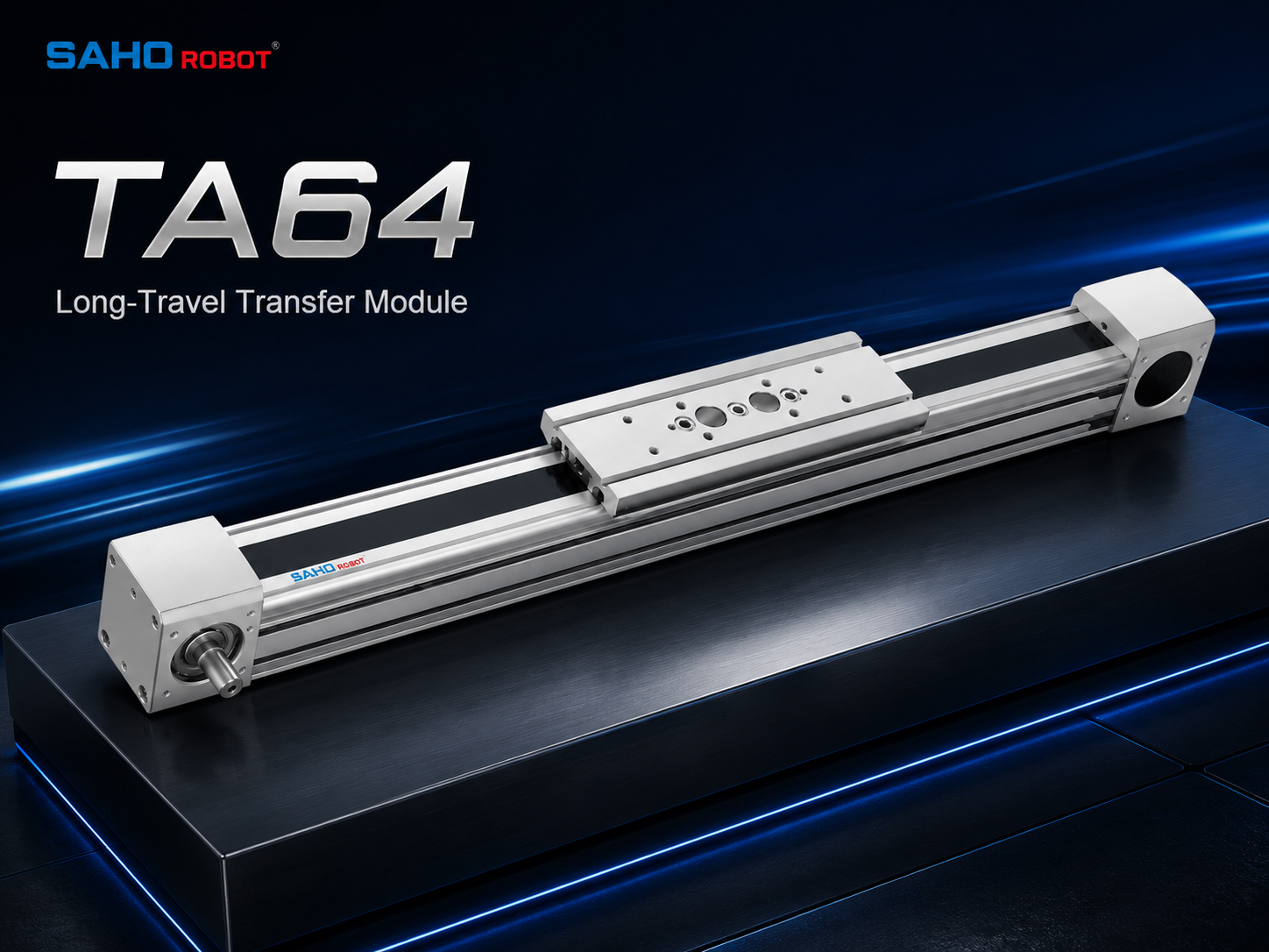
TA Series belt actuator for long-travel transfer layouts that need clean motion, practical speed, and easy maintenance.
Applications That Need Long Stroke and Stable Transfer
In lithium battery production, long-stroke modules can move trays, carriers, or fixtures between process stations. These loads may be wide and sensitive to vibration, so guide support and smooth acceleration are important. A stable axis helps protect both the product and the process rhythm.
In LCD and panel handling, travel distance can be long while the product shape is wide. Moment load and carriage stability should be checked carefully. A light panel may still create a large overturning force if the load center is far from the carriage center.
In photovoltaic automation, linear modules often support panel transfer, tooling movement, and loading positions. Long travel and repeatable stopping are common requirements. Dust, frame support, and cable movement can influence long-term reliability.
In packaging and general assembly, the axis may move light parts at high speed. The main challenge is often not the payload, but the acceleration profile and stopping behavior. A properly sized belt-drive module can help reduce wasted transfer time between operations.
In gantry systems, one long X-axis may carry a shorter Y-axis and a vertical Z-axis. The long axis becomes the foundation of the whole motion system. The guide rail, belt tension, frame flatness, and servo synchronization should be checked before installation.
Stroke Length: Confirm Effective Travel, Not Only Nominal Stroke
Effective travel should include the real working distance between positions. The mechanical system also needs extra room for acceleration, deceleration, home sensors, limit sensors, end clearance, and safe stopping. Nominal stroke and usable stroke should be checked separately.
A process may need a carriage to move 3,800 mm between stations. The full module length may still need additional space for the motor side, idle side, carriage length, cable track, and maintenance access. If the machine frame only allows a tight envelope, the module choice may change.
Long travel increases the influence of frame straightness. A module mounted on an uneven base may show rail stress, carriage resistance, or inconsistent height along the stroke. The mounting base should be flat, rigid, and supported across the full length.
A good stroke request should include effective travel, maximum total length, motor-side preference, cable direction, end sensor position, and working point locations. With these details, the selected module can match the actual equipment layout rather than only a catalog number.
Load Capacity: Weight, Center of Gravity, and Moment Load
Load capacity should never be described by weight alone. A compact 15 kg fixture centered on the carriage is very different from a 15 kg tray that extends far beyond the carriage plate. Although the weight is the same, the moment load can be much higher.
Selection data should show load weight, load size, mounting plate size, center of gravity, and overhang distance. The data should also state whether the load changes during the cycle. A carriage that picks up extra parts during travel has a changing inertia condition.
Load direction also matters. Horizontal mounting, side mounting, inverted mounting, and vertical mounting all stress the guide system in different ways. A module that works well horizontally may need a different motor, brake, or support plan in a vertical orientation.
For long-stroke material handling, the strongest selection method is to define both static load and dynamic load. Static load checks the carriage and rail support. Dynamic load checks acceleration, deceleration, emergency stop, belt tension, and servo torque margin.
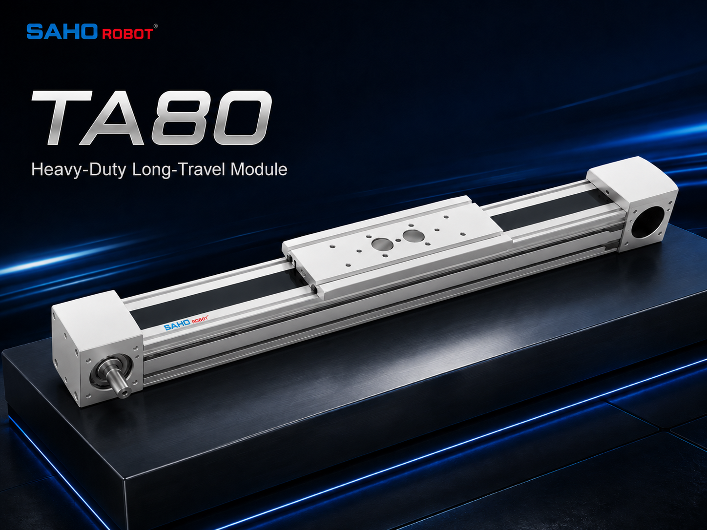
TA Series can be reviewed when the handling axis requires stronger structure, longer travel, and stable transfer under heavier moving load.
Sag and Deflection: Long Stroke Needs Proper Support
As stroke length increases, sag becomes a real mechanical issue. Sag means downward deflection caused by module length, support spacing, load position, and machine frame stiffness. Even a strong aluminum profile can move if the support points are too far apart.
Long-stroke axes should not rely only on end supports. Intermediate support, rigid mounting surfaces, and careful leveling help reduce deflection. In precision transfer, this can improve height consistency and carriage stability across the full travel.
In a gantry system, sag may also affect the upper axes. If the long X-axis flexes, the Y-axis and Z-axis may not repeat the same path through the full travel. The base axis should be treated as the main structure of the motion system.
Parallel-axis gantry layouts also require alignment between two long modules. If two axes are not square or synchronized, the beam can bind. The design should check mechanical parallelism, servo synchronization, frame stiffness, and installation tolerance together.
Belt Tension: Small Adjustment, Big Effect
Belt tension strongly affects motion quality. If tension is too low, the carriage may show vibration, unstable stopping, or reduced response during direction changes. If tension is too high, pulleys, bearings, and motor-side components may carry unnecessary stress.
Tension should match the stroke, payload, acceleration, and duty cycle. A short axis may be less sensitive, while a long axis may need more careful tension control. Repeated high-speed starts and stops can also make tension control more important.
Tension should also be considered during machine layout. A module placed in a blocked location may look compact, but it can make belt inspection difficult. Proper service access allows faster checks and more predictable operation.
During commissioning, belt tension should be checked together with servo tuning. Smooth motion depends on the mechanical drive and control settings working together. Belt condition, guide condition, motor inertia, and acceleration profile should be reviewed as one system.
Guide Support: The Rail Controls the Motion Path
The timing belt creates movement, but the guide system controls the path. The guide rail, slider, carriage plate, and module profile decide how steadily the load moves through the stroke. This is why guide support is critical in long-stroke handling.
For centered light loads, a standard carriage may be enough. Wide trays, offset fixtures, and gantry-mounted tooling may require stronger support. Rail size, slider length, carriage spacing, and mounting plate stiffness should be checked early.
Guide support also affects settling time. A module that reaches the position quickly may still need extra time to stop vibrating. If the process includes inspection, dispensing, assembly, or precise pickup, this settling time becomes part of the real cycle time.
A stable guide structure is especially important when the load has a high center of gravity. In that case, acceleration can create a rocking effect. A stronger rail and wider support layout may reduce vibration and improve process repeatability.
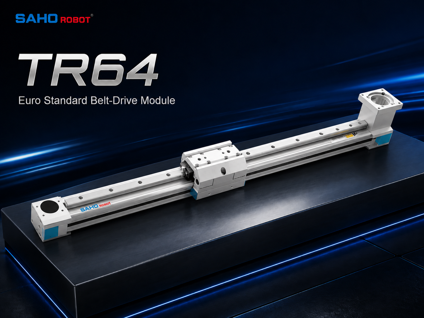
TR Series is suitable for Euro standard transfer layouts, compact gantry axes, and general belt-drive automation systems.
Servo Sizing: Match the Real Motion Profile
Servo sizing should start from the real motion profile, not only motor power. The calculation should include moving mass, pulley size, reducer ratio, friction, acceleration time, deceleration time, external force, and safety margin. These values decide the torque requirement and inertia match.
In many long-stroke handling systems, acceleration is more important than top speed. A process may request high speed, but the stroke may not allow a long constant-speed section. The axis may spend much of the cycle accelerating and decelerating.
Payload changes the motor demand quickly. A heavier carriage requires more torque during acceleration. A high center of gravity can add vibration. A long cable chain can increase moving resistance. These details should appear in the sizing data.
A complete servo review should include normal cycle, maximum cycle, emergency stop condition, vertical holding force when relevant, brake requirement, encoder feedback, drive compatibility, and cable movement. This helps the module and servo system work as one unit.
| Servo Sizing Item | What to Confirm |
| Moving mass | Carriage, product, fixture, tooling, adapter plate, cable carrier, and air tubes. |
| Motion profile | Maximum speed, acceleration, deceleration, dwell time, cycle time, and direction changes. |
| Load position | Center of gravity, overhang, height above carriage, and side offset. |
| Mounting direction | Horizontal, side-mounted, inverted, vertical, or gantry-mounted layout. |
| Control target | Repeatability, settling time, stop smoothness, vibration limit, and noise target. |
Installation Direction: Horizontal, Side, Inverted, and Vertical Use
Installation direction changes the mechanical and electrical requirements. A horizontal axis mainly handles moving mass and friction. A vertical axis must also handle gravity, brake selection, and safe holding force.
Side mounting needs careful review. When the load does not sit directly above the carriage, the guide system carries extra moment. Load offset, rail direction, carriage support, and mounting plate stiffness should be checked together.
Inverted mounting can keep the work area open, but it also requires attention to falling-object safety, debris control, cable routing, and service access. The clean appearance of an overhead layout should not hide maintenance points.
Vertical or inclined use should be confirmed with the actual load, stroke, speed, brake method, and safety requirement before final selection. A brake motor or mechanical lock may be required to prevent gravity drop depending on the application.
How to Choose Between SAHO TA Series and TR Series
SAHO TA Series and TR Series both belong to the belt-drive linear module direction. They should be considered for timing-belt driven carriage motion, not confused with direct-drive linear motor products. This distinction matters because the selection logic, structure, and application range are different.
TA Series is a strong starting point when the application needs long stroke, high-speed transfer, low-noise operation, and heavier material handling. It can support automation equipment, lithium battery production, LCD panel manufacturing, photovoltaic production, white goods assembly, and other industrial automation layouts.
TR Series is a suitable direction for Euro standard module layouts, transfer axes, machine loading, gantry travel, and general belt-drive automation systems. It can be reviewed when the design needs a standard structure with practical guide support.
The final series should not be chosen only by application name. The correct path is to compare stroke, payload, center of gravity, speed profile, mounting direction, support spacing, and service space. This prevents over-selecting or under-selecting the module.
| SAHO Series | Best-Fit Direction | Selection Focus |
| TA Series | Long-stroke, high-speed, low-noise, heavy-duty handling layouts. | Stroke length, speed profile, payload, belt tension, servo sizing, and maintenance access. |
| TR Series | Euro standard transfer, gantry, and general belt-drive module layouts. | Guide support, carriage stability, mounting direction, frame alignment, and load offset. |
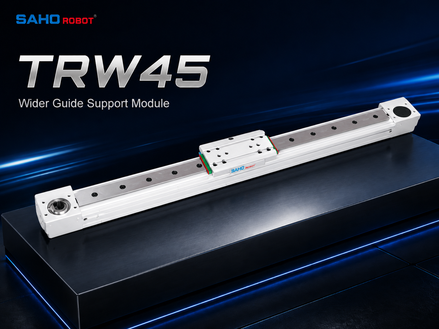
TR Series can be reviewed when the handling layout needs wider guide support, long travel, and stable movement in gantry or transfer systems.
Selection Checklist for Long-Stroke Material Handling
A reliable selection should use a clear data checklist. Define the effective stroke and the total space available. Then confirm the load weight, load size, center of gravity, and fixture mounting method.
Motion profile is just as important as travel length. Target speed alone is not enough. Acceleration time, deceleration time, dwell time, cycle time, and daily operating hours should also be included.
Accuracy and stability requirements should be stated clearly. Repeatability, stop tolerance, vibration limit, straightness, and settling time can change the module and servo recommendation. A transfer shuttle and an inspection feeder may not need the same performance level.
Installation direction and working environment should be provided together. Horizontal, vertical, inverted, dusty, low-noise, clean, or high-duty-cycle conditions can change belt tension, guide support, cover design, and maintenance planning.
| Data Category | Information to Prepare |
| Stroke and layout | Effective stroke, full length limit, working positions, motor side, sensor space, and end clearance. |
| Load condition | Weight, fixture size, center of gravity, overhang, load direction, and changing load during the cycle. |
| Speed profile | Maximum speed, acceleration, deceleration, dwell, cycle time, and duty cycle. |
| Accuracy target | Repeatability, stop tolerance, straightness, vibration level, and settling time. |
| Installation | Horizontal, vertical, side-mounted, inverted, gantry, support spacing, and frame condition. |
| Environment | Dust, temperature, noise target, cable routing, cleaning access, and maintenance space. |
Common Mistakes That Reduce Motion Quality
One common mistake is selecting by stroke and weight only. This ignores moment load, acceleration, mounting direction, and frame support. The axis may meet static data but perform poorly during real cycles.
Another mistake is using a weak or uneven mounting base. Long modules need support across the travel length. If the base twists or sags, the carriage can show resistance, vibration, or inconsistent height.
A third mistake is ignoring the cable carrier. Long travel means the cable chain, air tubes, and signal cables also move over a long distance. Their weight and resistance should be included in servo sizing and layout design.
Service access is often underestimated. Belt tension checks, guide cleaning, sensor replacement, and motor-side inspection should remain possible after the machine is assembled. A compact layout should not block the maintenance points that keep the line stable.
Product Recommendation Path
For long travel with higher speed, low-noise operation, and heavier material transfer, start with the TA Series page. It is the better starting point when the project needs extended stroke, stable transfer, and practical maintenance access in factory automation equipment.
For Euro standard transfer axes, gantry travel, and general belt-drive module layouts, review the TR Series page. It is useful when the design needs standard module structure, guide support, and model options for different transfer structures.
For final confirmation, the series choice should be checked by SAHO with real application data. Stroke, load, speed, accuracy, installation direction, center of gravity, duty cycle, and environment should be provided together. This avoids a selection based only on product appearance.
| Need | Recommended Starting Point | Next Step |
| Long stroke and high-speed transfer | TA Series | View TA Series |
| Euro standard transfer or gantry layout | TR Series | View TR Series |
| Unclear load, speed, or installation data | SAHO Robot engineering support | Contact SAHO |
FAQ
How long can a belt-drive linear module stroke be?
Stroke depends on the product series, load, speed, guide support, belt length, and installation base. For long-stroke material handling, the design should also include overtravel, sensor space, cable carrier movement, and maintenance access. Effective travel and total module length should be checked together.
What data is needed for long-stroke selection?
The selection should include stroke, moving load, load size, center of gravity, speed, acceleration, repeatability, installation direction, duty cycle, and working environment. Drawings should show motor side, cable exit, support spacing, and available installation space.
How do speed and payload affect the design?
Speed and payload affect moving inertia, belt tension, servo torque, guide load, and settling behavior. A light load at high speed may need vibration control. A heavier or offset load may need stronger guide support, smoother acceleration, and more torque margin.
When should TA Series be reviewed first?
TA Series should be reviewed first when the application needs long stroke, high-speed transfer, low-noise operation, and heavier material handling. It is suitable for automation equipment, lithium battery production, LCD panel manufacturing, photovoltaic production, white goods assembly, and similar industrial transfer systems.
When should TR Series be reviewed first?
TR Series should be reviewed first when the project needs a Euro standard belt-drive module for transfer axes, gantry movement, machine loading, or general industrial automation. The final choice should still check stroke, payload, load offset, mounting direction, and support spacing.
Conclusion: Choose the Axis Around Real Handling Data
Long-stroke material handling needs a complete selection method. Stroke, load capacity, sag, belt tension, guide support, servo sizing, and installation direction all influence the final result. A reliable design should begin with process data, then move into product series comparison.
For a stable belt actuator selection, SAHO should receive stroke, moving load, load size, speed, accuracy, installation direction, center of gravity, duty cycle, and environment details. With this information, TA Series and TR Series can be reviewed more accurately for long travel, material transfer, gantry movement, and industrial automation layouts.
Prepare a layout drawing with effective stroke, total length, motor side, cable path, and support points.
Define the complete moving load, including fixture weight, center of gravity, overhang, and cycle profile.
Confirm speed, acceleration, repeatability, installation direction, duty cycle, and environment before final model selection.
Need a Long-Stroke Material Handling Module Selection?Send SAHO the required stroke, moving load, target speed, accuracy, installation direction, center of gravity, duty cycle, mounting space, and working environment. The engineering team can review TA Series or TR Series options for the application. |







-
-
 English
 -
 Français
 -
 Deutschland
 -
 Italia
 -
 Polska
 -
 España
 -
 Русский язык
 -
 日語
日語 -
 한국
한국 -
 Türkiye
 -
 português
 -
 بالعربيةês
 -
 Tiếng Việt
 -
 คนไทย
คนไทย -
 简体中文
简体中文 -
繁體中文
-