

Date:2026-08-15 Click:249
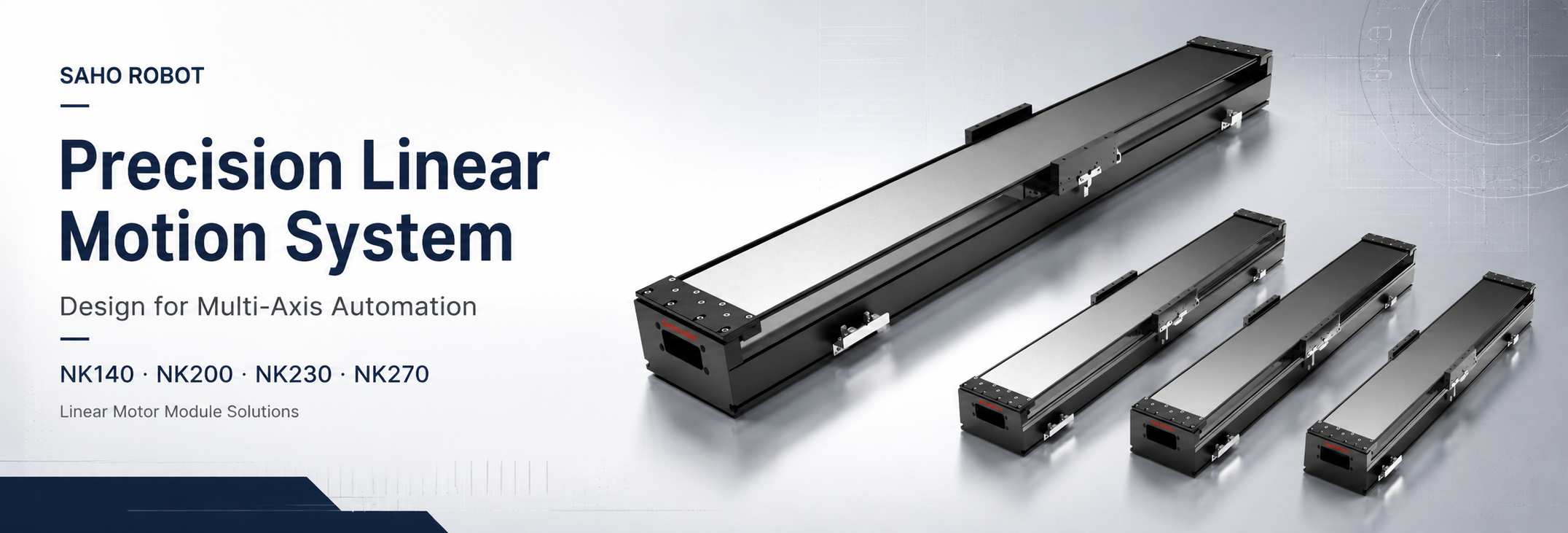
A Precision Linear Motion System for multi-axis automation is more than a single axis with a motor. It is a complete motion platform that connects axis layout, load path, stiffness, encoder feedback, cable routing, controller logic, and installation accuracy. Reliable XY, XYZ, and gantry design starts with real application data before any module is selected.
In modern automation equipment, every moving axis changes the demand placed on the axis below it. A Y axis mounted on an X axis becomes part of the X-axis moving load, while a Z axis adds gravity, tool offset, braking logic, and safety requirements. Stroke, payload, speed, acceleration, repeatability, installation direction, and cable path need to be reviewed as one system rather than as separate catalog values.
SAHO’s NK Series linear motor modules belong to the broader Linear Motor product direction. The NK Series uses direct drive motion with a steel belt protected module structure. It should not be confused with belt-driven or screw-driven linear modules, because those products use different transmission structures and require different selection logic.
| Design Topic | Key Data | SAHO Direction |
| XY stage, XYZ platform, gantry system, long stroke, and high-speed positioning | Stroke, load, moving mass, speed, acceleration, repeatability, environment, and cable route | NK steel belt linear motor modules and related linear motor solutions |
Designing a Precision Linear Motion System for Multi-Axis Automation
Multi-axis selection should begin with the process rather than the product model. A camera inspection stage, laser positioning table, semiconductor handling unit, battery production platform, dispensing machine, and TFT-LCD transfer system may use similar travel lengths, yet they can require very different motor force, guide stiffness, encoder configuration, controller tuning, and settling behavior.
In a single-axis project, travel, payload, and speed can be enough for an early concept review. A multi-axis platform needs a more complete load-transfer calculation. The lower axis carries the upper axis, tooling, fixture, workpiece, cable chain, air tube, sensor cable, and process head. This makes the real moving mass much higher than the nominal workpiece weight in many machines.
An XY system often uses a longer X axis as the base and a shorter Y axis as the cross axis. The Y axis may perform the finer process positioning, while the X axis provides longer travel. The X axis still has to accelerate and decelerate the complete Y-axis assembly during every cycle, so selecting X from workpiece load alone can underestimate thrust and stiffness demand.
An XYZ platform adds a vertical working direction. The Z axis may carry a camera, laser head, dispenser, nozzle, gripper, probe, or screwdriving tool. Gravity changes the force calculation, and the design may also need a brake, counterbalance, holding strategy, or controlled stop method depending on the machine architecture and safety requirement.
Gantry systems add another system-level problem: two parallel drive sides may move one bridge while another axis moves across it. If the parallel axes do not stay synchronized, the bridge can rack or twist. Guide load rises, tool-point accuracy can shift, and the mechanical structure may see repeated side loading. Bridge stiffness, frame squareness, feedback, homing logic, and emergency-stop behavior need to be planned together.
When Direct Drive Makes Sense in a Multi-Axis Platform
Direct drive is most useful when the machine needs fast response, repeatable positioning, controlled settling, and fewer mechanical transmission elements in the force path. A linear motor module does not use a timing belt, pulley, ball screw, or rack to convert rotary motion into linear motion. That can reduce backlash and transmission compliance in applications where dynamic response matters.
The practical advantage in a multi-axis machine is not simply higher speed. A stage must accelerate, stop, settle, and repeat the process without transferring excessive vibration to the camera, laser head, dispenser, probe, or fixture. In inspection, alignment, laser processing, electronics assembly, and battery equipment, settling time can be as important as top speed because the process cannot begin until the tool point is stable enough for the required tolerance.
An integrated steel belt linear motor module can also reduce the amount of mechanical integration work compared with a motor-only architecture. The module combines the direct drive system with a guide structure, moving table, base, and protection structure. This is useful when the machine builder wants a practical axis platform but still needs freedom to combine multiple axes into a custom XY, XYZ, or gantry layout.
Direct drive does not compensate for weak machine structure. A higher-thrust motor cannot correct poor mounting flatness, an undersized bridge, excessive cable drag, large off-center tooling, or an unrealistic acceleration profile. The correct question is not “Which motor is fastest?” but “Which axis structure can deliver the required tool-point motion after load, stiffness, cable, encoder, and control effects are included?”
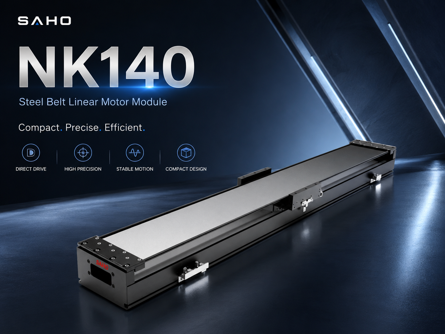
NK140 is a compact direct drive module direction for lighter tooling, inspection stages, and smaller multi-axis automation layouts where moving mass and installation space are limited.
XY, XYZ, and Gantry Layouts: Different Loads, Different Risks
XY systems fit flat working areas such as vision inspection, laser marking, dispensing, electronic component alignment, small-part transfer, and process positioning. The base X axis commonly provides the longer travel, while the Y axis performs cross movement. The design priority is to keep the upper assembly light enough for dynamic performance without sacrificing rigidity at the tool point.
XYZ systems add approach, height, focus, insertion, lifting, or process-force functions. Vertical motion needs a separate review because gravity is present even when the machine is not accelerating. Tool offset also becomes more important: a camera, gripper, nozzle, probe, or laser head mounted away from the carriage center creates a moment that can influence pitch, yaw, guide loading, and tool-point stability.
Gantry layouts support wide work areas, long-stroke processes, panel handling, battery equipment, solar equipment, large inspection stages, and automated loading systems. Their main challenge is not only payload. The bridge behaves as a structural member between two drive sides, so stiffness, mass distribution, frame squareness, dual-axis feedback, and synchronization strategy directly influence motion quality.
The layout should follow the process envelope. Use XY when the task is primarily planar, add Z only when the process needs controlled vertical motion, and choose a gantry when the work area or machine geometry requires a moving bridge. Adding axes without a clear process reason increases moving mass, cable complexity, calibration work, and controller demand.
| Structure | Suitable Use | Main Design Point |
| XY stage | Inspection, dispensing, laser marking, alignment, and flat transfer | Lower-axis moving mass, upper-axis rigidity, cable movement, and settling time |
| XYZ stage | Tool approach, height control, assembly, focusing, probing, and pick-and-place | Gravity load, Z-axis holding strategy, stiffness, brake logic, and tool offset |
| Gantry system | Long stroke, wide work area, panel handling, large inspection, and line automation | Bridge rigidity, mass distribution, dual-axis synchronization, and frame squareness |
NK200 for Balanced XY and XYZ Platforms
For medium-size XY and XYZ layouts, NK200 can be reviewed when the machine needs more structural and thrust margin than a smaller module while still keeping the upper axis reasonably compact. This direction can suit electronics assembly, laser positioning, inspection, dispensing, and process positioning where the moving upper axis or tooling creates a meaningful share of total moving mass.
NK200 should not be selected from width alone. Compare the complete moving assembly, acceleration profile, cable direction, mounting surface, required settling time, and process tolerance. A medium-size axis with poor load distribution can perform worse than a correctly sized smaller or larger platform.
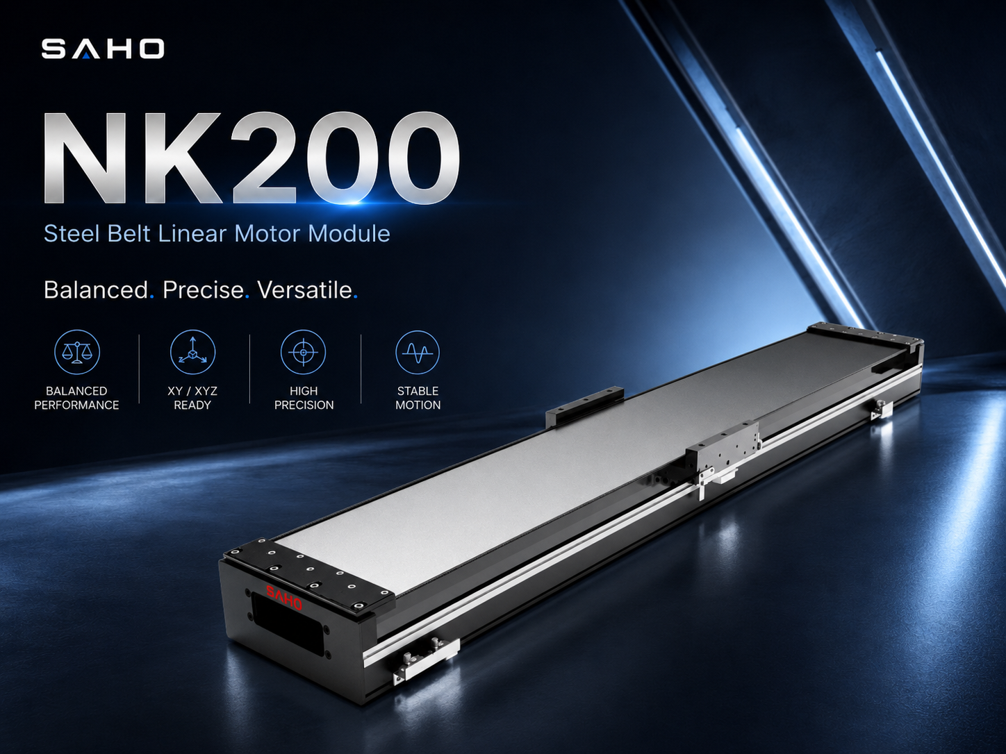
NK200 is positioned here as a balanced multi-axis module direction for XY and XYZ platforms that need additional moving-load and structural margin.
Accuracy Budget: How Error Builds Across Multiple Axes
Accuracy in a multi-axis machine is not controlled by one catalog value. The final tool-point result is influenced by guide straightness, frame flatness, encoder feedback, controller tuning, thermal behavior, tool offset, installation quality, and the geometry between axes. An accuracy budget should be defined before the axis model is approved.
Repeatability describes how closely an axis returns to the same position under similar conditions. It is important for inspection, dispensing, alignment, probing, and assembly, but it does not describe every geometric error in the platform. Straightness, squareness, pitch, yaw, roll, thermal drift, and fixture error can still move the tool point even when individual axes repeat well.
Long travel makes geometric error more visible. A camera inspection platform may return accurately to programmed positions while still showing tool-point variation from one end of the stroke to the other if the mounting base is uneven or the axis is not aligned correctly. In an XY system, X-axis straightness and X-to-Y squareness also combine at the process point.
Off-center tooling introduces another layer. A heavy camera, laser head, gripper, or dispenser mounted away from the carriage center creates moment load. The carriage may still reach the commanded encoder position, yet the tool can shift under acceleration, deceleration, process contact, or cable force. This is why the accuracy target should be stated at the tool point whenever possible, not only at the motor or encoder.
For specification work, separate repeatability, positioning accuracy, straightness, squareness, and tool-point tolerance. These values answer different questions. A machine builder that needs repeated camera positioning may prioritize repeatability and settling, while a long-travel measurement stage may place more weight on geometric accuracy and calibration across the full work envelope.
Practical accuracy budget checklist
Define repeatability and positioning accuracy at the tool point, not only at the carriage.
Separate axis error from frame, fixture, calibration, and process error.
Review straightness, squareness, pitch, yaw, and roll where they can affect the workpiece or sensor.
Calculate moment load created by off-center tooling, cables, brackets, and process heads.
Include temperature, mounting flatness, warm-up behavior, and calibration method in the tolerance budget.
Stiffness and Load Path: The Core of Stable Motion
A fast motor cannot solve a weak mechanical structure. In multi-axis automation, every force has to travel through the carriage, guide, connecting plate, upper axis, tooling, frame, and mounting surface. Any weak section in that load path can turn commanded acceleration into vibration, deflection, or longer settling time.
Static stiffness affects final position under load. The moving table, upper axis, workpiece, tool head, cable chain, brackets, and fixture all apply force to the lower structure. If the base or connecting plate deflects, the encoder may report the correct carriage position while the real process point is displaced.
Dynamic stiffness affects what happens during and immediately after motion. A structure can eventually settle at the commanded position yet still be unsuitable for a short-cycle inspection or assembly process if it vibrates for too long after each move. This is why acceleration, mass distribution, natural frequency, connection rigidity, and settling requirement belong in the same design discussion.
Gantry bridges require special attention because beam mass and beam stiffness pull the design in opposite directions. A lighter bridge reduces inertial demand but may flex or vibrate. A heavier bridge can improve rigidity but raises motor force demand and can reduce acceleration. The correct balance depends on span, tool position, payload distribution, speed profile, and the stiffness of the supporting frame.
Mounting support is part of the motion system, not an installation detail to solve later. A long axis placed on an uneven or weak frame can lose straightness and create guide preload variation. Support spacing, mounting flatness, bolt access, frame section, and local reinforcement should be reviewed before the machine base is released for fabrication.
| Stiffness Item | Why It Matters | Design Check |
| Base support | Controls straightness and long-stroke stability | Frame flatness, bolt spacing, support length, and local reinforcement |
| Moving load | Affects acceleration, vibration, thrust demand, and settling | Upper axis, tooling, cable chain, fixture, workpiece, and center of gravity |
| Bridge beam | Controls gantry deflection, vibration, and synchronization load | Span, mass, rigidity, payload location, and dual-axis control method |
NK230 for Longer Stroke and Heavier Moving Mass
For applications with heavier upper axes or longer strokes, NK230 can be reviewed as a stronger module direction. It can fit medium-to-heavy multi-axis platforms, battery equipment, panel handling systems, and process machines where the lower axis must carry more structure while maintaining direct drive response.
The selection should include moving mass and center of gravity, not static payload alone. A heavy tool may appear manageable at rest but can create substantially higher dynamic force during acceleration and deceleration. Motion profile, duty cycle, installation direction, support condition, and cable drag all influence the real requirement.
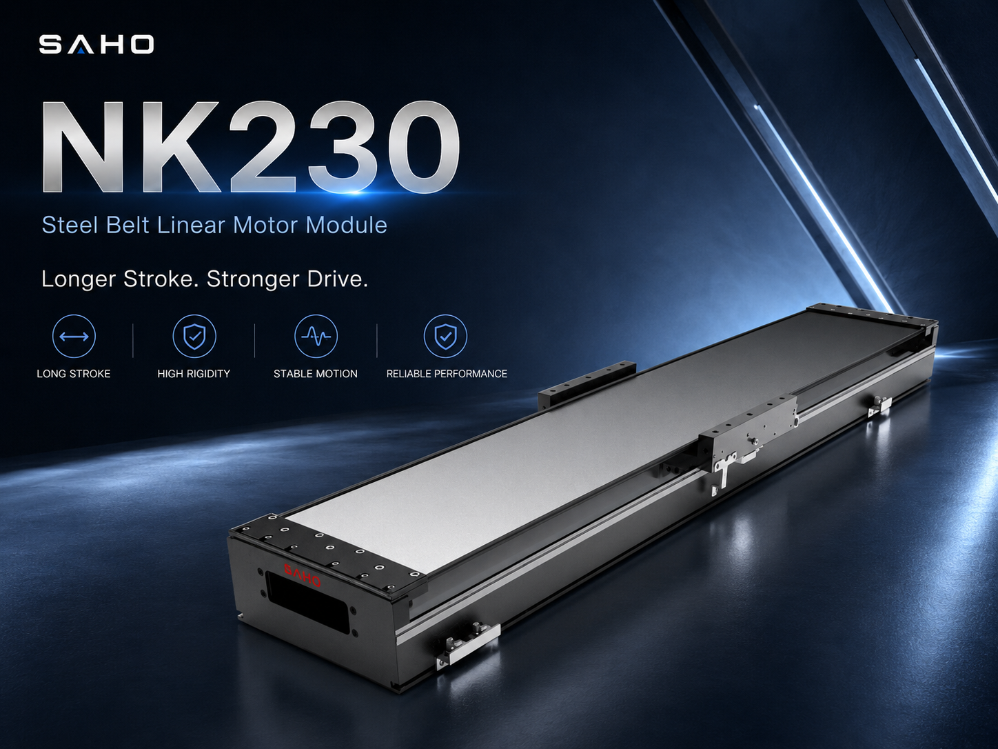
NK230 is a stronger direct drive module direction for longer travel, heavier upper-axis assemblies, battery equipment, and panel handling layouts.
Controller, Linear Motor, and Encoder Matching
Mechanical layout and control architecture have to be developed around the same motion profile. Motor thrust, drive capacity, encoder feedback, controller bandwidth, and structural stiffness all influence how closely the tool follows the commanded path. Payload and stroke alone are not enough to size the system.
Acceleration drives peak force demand. A light payload moving at modest acceleration may need limited thrust, while the same mass under rapid indexing can need much higher peak force. Short-stroke machines also need realistic acceleration and deceleration values because there may not be enough travel to reach the stated maximum speed before the axis has to slow down again.
Duty cycle controls the thermal side of the selection. An axis that moves occasionally creates a different continuous load from an axis that indexes every few seconds throughout a shift. Peak thrust, continuous thrust, drive capacity, dwell time, ambient temperature, and cooling condition should be reviewed together before the final configuration is approved.
Encoder resolution should also be matched to the mechanical system and process tolerance. Higher-resolution feedback can support fine control, but it cannot repair a flexible frame, poor guide alignment, excessive cable force, or a weak connection between axes. The feedback system should be chosen as part of an accuracy budget rather than as an isolated specification upgrade.
Gantry synchronization requires the controller to manage two mechanically linked drive sides as a coordinated pair. The axes must stay aligned during acceleration, constant speed, deceleration, homing, recovery, and emergency stop. Position feedback, homing strategy, allowable skew, bridge stiffness, and fault handling should be agreed before the gantry frame and electrical architecture are finalized.
| Control Item | Why It Matters | Required Data |
| Motor thrust | Supports acceleration and load movement | Moving mass, acceleration, installation direction, stroke, and cycle time |
| Servo drive | Handles peak demand and continuous thermal load | Move distance, speed, acceleration, duty cycle, and ambient temperature |
| Encoder | Provides position feedback for motion control | Accuracy target, resolution need, environment, cable route, and installation geometry |
| Controller | Coordinates trajectory, interpolation, synchronization, and safety logic | Axis count, gantry logic, I/O, communication method, homing strategy, and fault response |
Cable Management: A Small Detail with Large Motion Consequences
Cable routing should be designed while the axis layout is still flexible. Motor cables, encoder cables, sensor cables, air tubes, vacuum lines, camera cables, and lighting cables all add moving mass. They also create drag, bending resistance, side force, and maintenance constraints that can change along the stroke.
A drag chain should not become an uncontrolled load on the motor. If resistance changes as the chain opens and closes, speed ripple or small positioning differences can appear. Long-stroke equipment should define chain support, bend radius, moving-end location, fixed-end location, cable fill, and spare capacity before the final axis length and guarding are fixed.
Electrical routing also affects feedback reliability. Motor power, encoder, sensor, camera, laser, and other signal cables may have different shielding and separation requirements. Good grounding, connector placement, strain relief, and routing practice reduce the chance that an otherwise stable mechanical system becomes difficult to tune or troubleshoot because of electrical noise.
Service access matters after commissioning. Home sensors, limit sensors, connectors, cable clamps, drag-chain brackets, end covers, and feedback components should remain reachable without dismantling large sections of the machine. A layout that is compact on CAD but inaccessible in production can increase downtime during inspection, adjustment, or replacement.
Gantry layouts multiply these issues because the bridge may carry motor cables, encoder lines, air tubes, vacuum pipes, lighting cables, cameras, and process tools at the same time. Reserve cable space before bridge width, guarding, and tool plates are finalized so the cable path does not interfere with the moving envelope or create an unexpected moment load.
Application Data Needed Before SAHO Selection
A useful motion proposal needs complete application data. Without it, module selection becomes a guess based on nominal load or travel. Prepare an axis table before choosing module width, motor thrust, stroke, controller configuration, and multi-axis arrangement.
Stroke should include the real working travel plus the space required for homing, limit sensing, tool clearance, cable movement, and safety margin. A 1000 mm process travel does not automatically mean a 1000 mm total machine requirement. Effective stroke, total module length, end clearance, and the machine envelope should be checked separately.
Load data should include every component that moves with the axis: upper axes, tooling, brackets, grippers, cameras, cable chains, tubes, sensors, fixtures, workpieces, and protective structures. State the center of gravity when the load is not centered on the carriage, especially for tall tools or overhung process heads.
Speed should be connected with acceleration, deceleration, move distance, cycle time, dwell time, and settling time. A high catalog speed may provide little benefit in a short-stroke process if the axis spends most of the move accelerating and decelerating. The useful metric is the complete motion cycle, not maximum speed by itself.
Accuracy requirements need the same clarity. Repeatability, absolute positioning accuracy, straightness, squareness, and tool-point tolerance are different specifications. The proposal should identify which value controls process quality and whether calibration at the machine level is planned.
Environment can change the mechanical and electrical configuration. Dust, oil mist, temperature, vibration, process debris, clean-area requirements, available installation space, and maintenance access should be stated early. Steel belt protection can be useful where the application needs better coverage of the motion structure, but the complete environment still needs to be reviewed rather than assumed from the cover alone.
| Selection Data | What to Confirm | Why It Matters |
| Stroke | Working travel, home position, sensor distance, overtravel, and safety margin | Prevents module-length errors, lost working space, and tool collision risk |
| Load | Tooling, upper axes, workpiece, cable chain, brackets, and center of gravity | Defines thrust, guide load, moment load, stiffness demand, and lower-axis moving mass |
| Motion profile | Speed, acceleration, deceleration, move distance, cycle time, dwell, and settling | Determines dynamic force, thermal demand, and controller tuning direction |
| Accuracy | Repeatability, absolute accuracy, straightness, squareness, and tool-point tolerance | Controls feedback choice, frame requirements, alignment, and calibration planning |
| Environment | Dust, temperature, oil mist, vibration, process debris, and space limits | Affects protection structure, cable route, maintenance access, and installation method |
For faster SAHO selection support, prepare the axis layout, stroke, complete moving mass, target speed, acceleration, cycle time, repeatability or tool-point tolerance, installation direction, cable-chain direction, controller requirement, and working environment. This gives the engineering team enough context to compare module directions against the real machine instead of a general catalog condition.
NK270 for Gantry and High-Load Direct Drive Platforms
For large gantry systems and high moving-mass platforms, NK270 can be reviewed when the lower axis or gantry drive needs stronger structural and thrust margin. This direction is relevant to wide work areas, heavy bridge structures, long-stroke motion, large tooling, and demanding direct drive equipment where the module becomes part of a larger machine frame.
Large-axis selection should include dimensional planning from the beginning. Mechanical limits, mounting holes, slide-table size, total module length, cable space, support spacing, bridge interface, and maintenance access all affect the final frame. The module drawing should be reviewed together with bridge stiffness and controller synchronization before the machine structure is frozen.
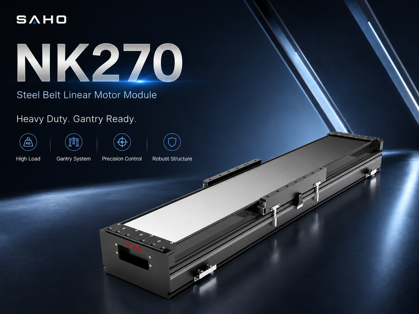
NK270 is positioned here for gantry structures, wide work areas, higher moving mass, and larger direct drive platforms that need more structural margin.
Application Scenarios: What Changes in the Multi-Axis Design
In semiconductor and precision inspection equipment, the important question is usually not whether the axis can reach the position once, but whether the camera, sensor, probe, or handling head can return and settle consistently across repeated cycles. That places more emphasis on vibration control, geometric alignment, feedback stability, cable force, and calibration across the working area.
Laser processing adds another constraint: the tool path and focus relationship can be sensitive to frame motion and tool offset. High-speed travel is useful only when the axis can decelerate and stabilize without moving the process point outside the required tolerance. Long or wide laser machines also need careful straightness and gantry synchronization planning.
Dispensing and electronics assembly often use shorter repetitive moves with frequent direction changes. The selection should focus on acceleration, cycle time, moving tool mass, nozzle or head offset, cable and tube drag, and settling before dispensing or placement begins. A module that looks oversized from static payload alone may still be justified by the dynamic cycle, while an unnecessarily heavy upper axis can reduce the performance of the complete XY platform.
Lithium battery production and panel handling can combine longer strokes with larger fixtures, trays, cells, welding heads, inspection cameras, or loading devices. The lower axis may carry a significant upper assembly, so thrust margin, base support, protection, cable movement, and production duty cycle deserve more attention than workpiece weight alone.
TFT-LCD, solar, and other wide-panel systems often favor gantry layouts because the work area is broad. Here, bridge stiffness, span, squareness, long-stroke straightness, dual-axis synchronization, and cable routing become primary design variables. These applications show why a multi-axis direct drive system should be selected from the machine geometry and process path rather than by comparing single-axis load ratings in isolation.
How to Select Each Axis in a Multi-Axis Platform
Start with the base axis because it usually carries the greatest moving mass. Include the upper axis, connecting plate, fixture, tool, workpiece, cable chain, sensors, hoses, and any moving protection. Check thrust margin, guide support, mounting rigidity, base width, support spacing, and cable clearance against the required acceleration profile.
The cross axis should remain as light as practical while preserving rigidity. It often moves shorter distances and may require faster directional changes than the base axis. The connecting plate between axes must preserve squareness and resist deformation, while the cable route should avoid pulling the carriage sideways across the working area.
A vertical axis requires a separate gravity and safety review. Define the moving tool mass, center of gravity, holding requirement, brake or counterbalance strategy, process force, stopping behavior, and safe condition after power loss. Static payload alone is not enough for Z-axis approval.
For a gantry pair, treat the two drive sides and bridge as one mechanical system. Bridge span, beam mass, payload location, frame squareness, guide alignment, encoder feedback, homing method, synchronization logic, and fault response all affect the allowable skew and load on each side.
The tool interface should be checked last against the process point. A camera, dispenser, laser head, gripper, nozzle, measuring probe, or custom fixture can add mass and moment load far from the carriage center. Confirm bracket stiffness, mounting pattern, tool offset, cable exit direction, service access, and actual tolerance at the point where the process occurs.
| Axis Role | Common Requirement | Selection Direction |
| Base X axis | Long travel and complete upper-axis support | Prioritize full moving mass, thrust margin, stiffness, mounting flatness, and cable clearance |
| Cross Y axis | Fast cross movement and process positioning | Balance low moving mass, rigidity, squareness, and cable routing |
| Vertical Z axis | Tool approach, focusing, lifting, insertion, and height control | Check gravity load, holding strategy, brake need, tool offset, and safe stop behavior |
| Gantry pair | Wide work area and bridge movement | Confirm bridge stiffness, dual-axis synchronization, frame squareness, homing, and fault response |
Related SAHO Products for Direct Drive Multi-Axis Automation
The SAHO NK Series is a steel belt protected linear motor module family that integrates direct drive motion, guide structure, moving table, base, and protection into a practical axis platform. These modules can be used as individual axes or combined into XY, XYZ, and gantry structures when the machine design needs an integrated direct drive approach.
The four models shown in this article should be treated as selection directions rather than fixed application rules. NK140 suits more compact and lighter-axis concepts; NK200 provides a middle direction for common XY and XYZ platforms; NK230 adds room for longer travel or heavier upper assemblies; NK270 is the larger direction for gantry and high moving-mass platforms. Final selection still depends on the actual stroke, motion profile, installation, load distribution, and accuracy requirement.
SAHO also provides separate linear motor categories for machine builders that need a motor-only architecture. That route is different from choosing an integrated NK module. A custom motor-only design also needs guide rails, base structure, encoder installation, protection, cable management, moving table design, alignment, and machine-level integration.
Choose the NK direction when an integrated steel belt protected direct drive module is the better fit for the machine architecture. Review separate Linear Motor products when the project requires a custom guide, base, moving table, protection, and feedback arrangement. Keeping these two architectures separate avoids mixing linear motor modules with belt-driven or screw-driven transmission products.
| SAHO Product | Product Type | Suitable Design Direction |
| NK140 | Steel belt linear motor module | Compact XY stage, lighter tooling, inspection, and smaller direct drive axes |
| NK200 | Steel belt linear motor module | Balanced XY and XYZ platforms, electronics assembly, laser positioning, and inspection |
| NK230 | Steel belt linear motor module | Longer stroke, heavier upper-axis assemblies, battery equipment, and panel handling |
| NK270 | Steel belt linear motor module | Gantry axes, high moving mass, wide work areas, and larger direct drive platforms |
Integration Notes Before the Machine Design Is Frozen
The axis is only one part of the finished machine. The frame, guarding, fixture, tooling, electrical cabinet, controller, safety circuit, air system, software, and maintenance access all influence final performance. Integration review should begin while there is still time to change the mechanical layout rather than after drawings are released.
The mounting surface should be flat, stable, and accessible. A precision axis mounted on a weak base can lose straightness or show inconsistent guide loading. Installation flatness, bolt spacing, support length, frame stiffness, and service access should match the axis length and the complete moving load.
Reserve space for covers, sensors, cable chains, connectors, end plates, and replacement access. A compact machine envelope is useful only if critical components can still be inspected and serviced. This is especially important on nested XY and XYZ platforms where an upper axis can block access to the lower axis after assembly.
Include enough safety and overtravel distance around the working stroke. Home position, limit position, emergency overtravel, cable bend, tool clearance, guarding, and fixture access all add to the real machine envelope. Total equipment length should not be calculated from the process stroke alone.
Plan the electrical cabinet with the motion platform. Linear motor drives need suitable power, grounding, heat management, encoder connection, communication, I/O, and safety logic. Early electrical planning also helps define cable length, connector location, cabinet position, and the control strategy for multi-axis interpolation or gantry synchronization.
FAQ
What is a precision linear motion system in multi-axis automation?
It is a complete motion structure in which one or more linear axes, guides, feedback devices, drives, controller functions, mounting structures, cables, and tooling work together to deliver the required motion at the process point. In an XY, XYZ, or gantry machine, system performance depends on how these parts interact rather than on a single motor or axis specification.
What information should be prepared before selecting the base and upper axes?
Prepare the axis layout, working stroke, complete moving mass, center of gravity, speed, acceleration, cycle time, settling requirement, accuracy target, installation direction, cable direction, environment, and available machine space. For the base axis, include the full upper-axis assembly rather than only the workpiece payload.
When is an NK linear motor module more suitable than a belt- or screw-driven module?
Review the NK direction when the machine benefits from an integrated direct drive linear motor module with fast response, repeatable positioning, controlled settling, and a steel belt protected structure. Belt- and screw-driven modules can still be suitable for other motion tasks, but they use different transmission structures and should be selected with their own speed, thrust, accuracy, maintenance, and duty requirements.
Why can cable routing affect multi-axis accuracy and settling?
Cable chains, hoses, and moving wires add mass and can apply drag or side force that changes with position. They can also introduce vibration or electrical-noise problems if routing is poor. Bend radius, cable weight, chain direction, fixed and moving ends, shielding, strain relief, and maintenance space should be defined before the final axis layout is released.
Summary and Selection Advice
Multi-axis direct drive automation should be selected from the process point outward. Define the motion envelope and tolerance, calculate the real moving mass on each axis, check the load path and stiffness, then confirm the motion profile, encoder, controller, cable route, and installation structure. This sequence keeps the design focused on the finished machine rather than on isolated catalog values.
For SAHO projects, the NK Series is the integrated steel belt protected direct drive module direction, while separate Linear Motor products support more customized motor-and-guide architectures. Within an NK-based multi-axis platform, the model still has to be matched to stroke, moving mass, acceleration, accuracy, stiffness, installation, and the role of that axis in the complete XY, XYZ, or gantry structure.
Base axis: calculate the complete upper assembly and prioritize thrust margin, stiffness, mounting flatness, and cable clearance.
Cross or vertical axis: control moving mass and tool offset while checking acceleration, gravity, holding strategy, and process-point tolerance.
Gantry: treat both drive sides, bridge stiffness, squareness, feedback, homing, and synchronization as one system.
Before quotation: prepare stroke, load, center of gravity, speed, acceleration, cycle time, accuracy target, installation direction, environment, cable route, and layout drawings.
Contact SAHO for Multi-Axis Linear Motor Module SelectionFor a multi-axis Precision Linear Motion System proposal, send SAHO your axis layout, stroke, complete moving mass, center of gravity, speed, acceleration, cycle time, repeatability or tool-point tolerance, installation direction, cable-management plan, controller requirement, and working environment. These details allow the engineering review to compare NK Series modules, Linear Motor options, and the integration requirements of the real machine. Contact SAHO |







-
-
 English
 -
 Français
 -
 Deutschland
 -
 Italia
 -
 Polska
 -
 España
 -
 Русский язык
 -
 日語
日語 -
 한국
한국 -
 Türkiye
 -
 português
 -
 بالعربيةês
 -
 Tiếng Việt
 -
 คนไทย
คนไทย -
 简体中文
简体中文 -
繁體中文
-