

Date:2026-08-17 Click:262
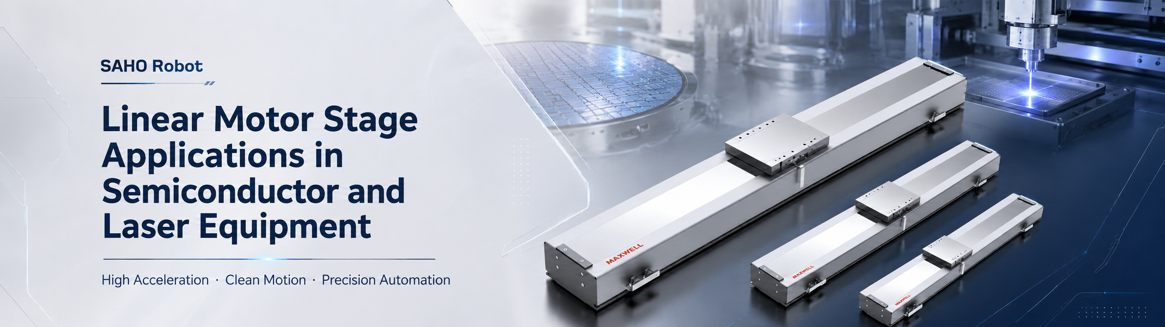
Selecting a linear motor stage for semiconductor and laser equipment starts with the process, not with maximum speed or motor size alone. A Linear Motor Stage can support high acceleration, clean motion, and stable positioning when short cycle time, low mechanical wear, and repeatable motion are more important than a simple mechanical transmission. In SAHO’s product structure, this application direction belongs to the Linear Motor category, especially the NK and MNK linear motor module series.
Meanwhile, this article keeps linear motor products separate from belt driven or screw driven linear modules. NK and MNK modules use a direct drive linear motor system. The protection structure is not a timing belt transmission. As a result, the product direction is different from belt type linear actuators and ball screw linear actuators.
For semiconductor and laser equipment, stage selection should start from the real process. Stroke, moving load, acceleration, speed, positioning accuracy, installation direction, cable routing, and machine base rigidity all affect the final result. The best model is not always the largest one or the fastest one. It is the model that fits the working cycle, load condition, and equipment layout.
View NK Series View MNK Series Contact SAHO for Selection
Why Direct Drive Motion Fits Semiconductor and Laser Equipment
First, semiconductor equipment often works with small parts, tight positioning paths, and repeated inspection cycles. Wafer inspection, die sorting, chip handling, probe motion, and packaging inspection all need controlled movement. Therefore, vibration, backlash, and slow settling can affect inspection stability.
In a mechanical transmission system, the motor output passes through parts such as a screw, nut, belt, pulley, or coupling. However, a direct drive linear motor moves the carriage through electromagnetic force. This helps reduce transmission backlash and improves response during fast starts and stops.
At the same time, laser processing equipment needs smooth movement during cutting, welding, marking, trimming, and scanning. The laser path may include straight lines, curves, repeated marks, and fast direction changes. This means the motion stage has a direct effect on edge quality, mark position, weld consistency, and cycle time.
In addition, semiconductor production and laser processing both require stable automation around sensitive process areas. For broader semiconductor industry background, SEMI provides industry resources and standards information. For equipment motion design, this means the stage should support repeatable integration, clean movement, and long-term reliability.
Key Benefits of SAHO Direct Drive Linear Motor Modules
High Acceleration for Shorter Cycle Time
High acceleration helps an axis reach the target speed faster. This matters in inspection systems because many moves are short. Acceleration and settling time often matter more than top speed alone.
For example, a camera stage may move between many inspection points in one cycle. Each movement needs to start, stop, settle, and capture data. If the stage settles faster, the inspection cycle can improve without changing the camera, lens, or image software.
Clean Motion with Low Mechanical Wear
Second, direct drive motion reduces mechanical transmission parts. Ball screw and belt drive axes still fit many automation tasks. However, semiconductor inspection and laser processing often need smoother response and fewer wear points.
Sealed or protected linear motor modules can help reduce the effect of dust and particles around the moving structure. This is useful in compact precision equipment where stable motion and low maintenance are both important. Therefore, the module should match the real environment, not only the force requirement.
Smooth Scanning for Inspection and Measurement
Third, smooth scanning supports better inspection data. Cameras, laser sensors, line scan systems, and metrology heads may collect data while the axis is moving. Speed ripple, vibration, and unstable deceleration should be reduced as much as possible.
For AOI or wafer inspection, a stable moving path helps keep the optical distance predictable. In metrology systems, steady positioning helps protect measurement repeatability. As a result, the motion stage becomes part of the process quality, not only a transport component.
Multi-Axis Integration for Compact Equipment
Many precision machines need more than one axis. Semiconductor inspection, laser cutting, laser marking, electronic assembly, and panel processing may use XY, XYZ, stacked, or gantry structures. Therefore, a compact module design can simplify mechanical integration.
For a multi-axis system, the lower axis carries the upper axis and the process load. This means the moving mass calculation must include the complete stacked structure. Cable chain direction, sensor position, and safety cover space should also be planned before the frame layout is finalized.
Semiconductor Inspection Applications
Wafer Inspection and AOI Scanning
First, wafer inspection and AOI scanning require steady motion during data capture. A camera or sensor may move across wafers, substrates, panels, or electronic components. Velocity stability, low vibration, and repeatable position control are important.
In this type of machine, the stage may repeat the same movement pattern for long operating hours. Smooth acceleration helps reduce shock on optical parts. Direct drive motion helps reduce backlash from the mechanical transmission path.
Die Sorting, Chip Handling, and Packaging Inspection
Next, die sorting and chip handling systems need compact movement with reliable positioning. The moving load may include a nozzle, a fixture, a camera head, or a lightweight handling mechanism. Therefore, the selected stage must match both payload and moment load.
In packaging inspection, the stage may index between many positions within one cycle. Short settling time allows the camera to capture images sooner. However, the machine base must be rigid enough to support fast movement without extra vibration.
Probe Motion, Metrology, and Sensor Alignment
Also, probe motion and metrology require stable positioning around small features. The stage may carry a sensor, optical head, probe unit, or precision fixture. Repeatability, straightness, encoder feedback, and tuning quality should be reviewed early.
For these systems, a direct drive module should not be selected only by thrust. Instead, the complete working condition should be reviewed. This includes stroke, load center, encoder plan, servo control, cable movement, and mounting surface quality.
Laser Processing Applications
Laser Cutting and Glass Processing
Laser cutting equipment needs smooth motion while the laser path changes direction. The machine may process metal sheets, glass panels, films, ceramics, or electronic parts. Therefore, the axis should support fast movement and stable contour control.
SAHO’s Laser Industry page connects linear motor technology with laser precision cutting, welding, marking, and multi-dimensional processing. This matches equipment that needs high speed, high acceleration, and accurate path control.
Laser Marking, Welding, and Micro-Processing
Laser marking and welding systems often move between repeated points. The stage may carry the workpiece, the laser head, or an optical assembly. Starts, stops, and direction changes should remain smooth and predictable.
In micro-processing, small motion errors can appear as mark offset, uneven edge quality, or welding inconsistency. As a result, acceleration, jerk control, load mass, and frame rigidity should be balanced together. A strong motor cannot solve a weak machine structure alone.
Laser Inspection and Optical Scanning
In addition, some laser systems use scanning for measurement or inspection. The motion path must remain smooth while the sensor collects data. Therefore, velocity ripple, vibration, and cable drag should be controlled from the beginning of the design.
For optical scanning, the stage should also protect the alignment of cameras, lenses, sensors, and laser components. A compact direct drive module helps reduce mechanical complexity. Meanwhile, a clear cable path helps prevent interference inside the equipment.
Which SAHO Linear Motor Module Fits Which Equipment?
SAHO’s NK Series and MNK Series belong to the direct drive linear motor product direction. NK focuses on steel belt protected linear motor module applications. MNK focuses on sealed linear motor module applications where clean, smooth, and low-wear motion is required.
Model selection should follow real process data. Smaller frames can fit compact inspection and light optical motion. Larger frames can support higher thrust, wider tooling, heavier moving parts, and more demanding acceleration profiles. Before comparing frame sizes, it helps to decide whether the equipment is better matched to the NK or MNK product direction.
| Selection point | NK Series direction | MNK Series direction |
| Protection structure | Steel belt protected direct drive stage | Sealed linear motor module structure |
| Typical equipment priority | Compact precision stages, inspection motion, laser positioning, and direct drive applications where a protected stage structure fits the machine layout | Clean or protected precision motion, longer travel layouts, and equipment where sealing, cable planning, and multi-axis integration are important |
| What to compare first | Stroke, moving load, acceleration, accuracy, available installation space, and required protection | Stroke, moving load, protection requirement, cable routing, duty cycle, and XY/XYZ/gantry structure |
| When not to decide by series name alone | If force, travel, center of gravity, installation direction, or thermal load is close to a limit, compare the actual motion profile and mechanical layout before choosing the final frame size. | |
| SAHO model direction | Suitable equipment direction | Selection focus |
| MNK140 | Compact inspection, small optical stage, light handling, short-cycle scanning | Moving mass, compact footprint, cable path, short settling time |
| MNK200 | Medium load laser processing, long stroke inspection, panel scanning | Acceleration, guide load, stroke, process speed, frame rigidity |
| MNK230 | Higher thrust stage, wider table, larger laser head, precision platform | Payload, moment load, servo tuning, base stiffness |
| MNK270 | Large platform, heavy moving load, demanding laser and inspection equipment | Peak force, heat control, safety margin, installation base |
MNK140 for Compact Inspection and Light Optical Motion
First, MNK140 fits compact equipment layouts where the moving mass is moderate. It can support camera movement, small optical inspection, light handling, and high-speed indexing. It is a practical choice when machine space is limited but response speed remains important.
In semiconductor inspection, MNK140 can support short-cycle movement between many inspection points. In laser marking or small precision scanning, it can move a light worktable or process head. However, the fixture should stay balanced over the moving table to reduce moment load.
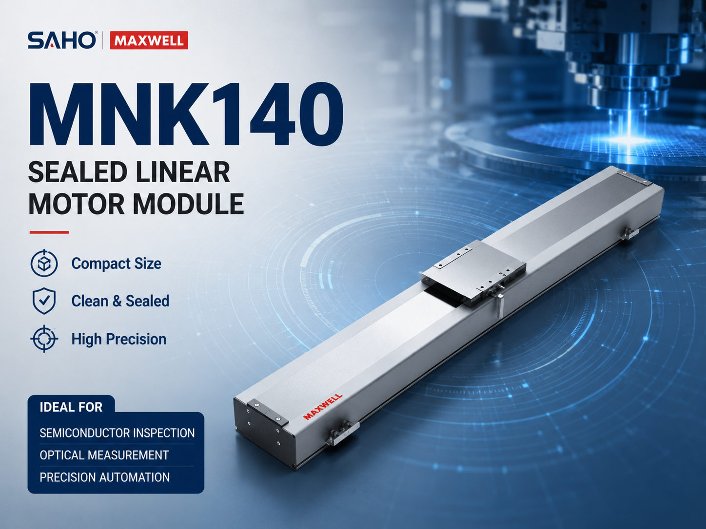
MNK140 sealed linear motor module for compact precision motion, inspection stations, and clean direct drive equipment layouts.
MNK200 for Medium Load Laser and Inspection Motion
Next, MNK200 suits medium load equipment that needs higher thrust than a compact frame. It can support laser processing, panel inspection, long stroke scanning, and electronic manufacturing equipment. This means it is often considered when speed and load both increase.
For laser equipment, MNK200 can help move a worktable or processing head along a stable path. For inspection systems, it can support longer travel with repeated movement. Still, acceleration should match the machine frame and the actual moving payload.
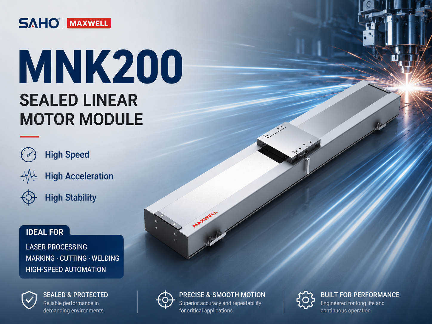
MNK200 sealed linear motor module for medium load laser processing, inspection motion, and clean high-speed automation systems.
MNK230 for Higher Thrust and Wider Stage Structures
For higher thrust needs, MNK230 provides a stronger direct drive platform. It fits wider tables, larger fixtures, heavier optical heads, and more demanding acceleration profiles. Therefore, it can support precision laser platforms and larger inspection stations.
However, a higher thrust model still needs a rigid base. If the mounting structure bends or vibrates, process accuracy may drop. Base design, guide load, center of gravity, and servo tuning should be reviewed together.
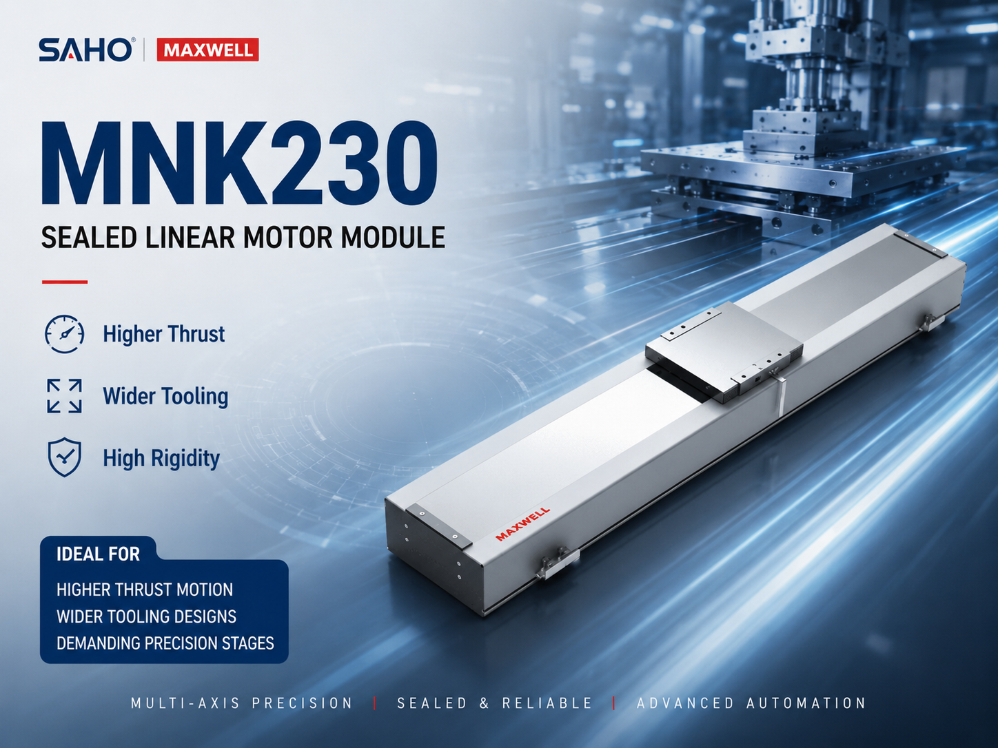
MNK230 sealed linear motor module for higher thrust motion, wider tooling, and demanding precision stage structures.
MNK270 for Large Precision Platforms and High Force Motion
Finally, MNK270 fits larger precision platforms and high force motion requirements. It can support heavier moving loads when the machine structure is designed correctly. Therefore, it is suitable for large laser equipment, wide inspection systems, and demanding industrial automation lines.
At the same time, high force motion brings more design responsibility. Heat, duty cycle, cable path, installation surface, and safety margin must be checked early. Otherwise, the stage may be limited by structure instead of motor capacity.
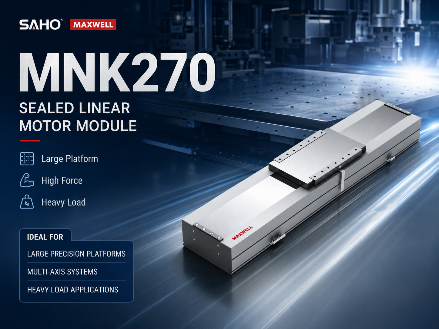
MNK270 sealed linear motor module for large precision platforms, high force motion, and heavy moving load applications.
How to Select a Linear Motor Stage for Semiconductor and Laser Equipment
1. Start with Stroke and Working Area
Stroke selection should follow the actual working area. Semiconductor inspection may need short, accurate travel. Laser cutting or panel processing may require longer travel and wider working space.
The design should reserve space for acceleration, deceleration, limit sensors, and mechanical safety clearance. If the working travel uses the full mechanical stroke, the system may have no margin. The selected stroke should include safe allowance.
2. Calculate Moving Load and Center of Gravity
Second, moving load should include every part that moves with the carriage. This may include a worktable, adapter plate, camera, lens, laser head, bracket, cables, air tubes, vacuum fixture, and sensor parts. As a result, the real moving mass can be higher than the main tool weight.
Moreover, center of gravity affects guide load and dynamic stability. A tall bracket or side-mounted tool can create extra moment load. Therefore, the load position should be shown clearly when selecting the model.
3. Balance Speed, Acceleration, and Settling Time
Third, speed should not be reviewed alone. A stage may offer high maximum speed, but short travel may never allow the axis to reach that speed. In that case, acceleration and settling time have more influence on cycle time.
For example, an inspection stage may move 50 mm, stop, capture an image, and move again. If vibration continues after each stop, the camera must wait. Smooth deceleration and rigid mounting are very important.
4. Confirm Accuracy, Repeatability, and Encoder Feedback
Accuracy and repeatability should match the process result. Accuracy describes how close the stage reaches the commanded position. Repeatability describes how consistently the stage returns to the same position.
In semiconductor inspection, repeatability helps keep measurement data consistent. In laser contour processing, path control and velocity stability also matter. Therefore, encoder feedback, controller capability, and servo tuning should be discussed together.
5. Review Installation Direction and Base Rigidity
Also, installation direction changes the load condition. A horizontal stage carries weight differently from a vertical or side-mounted stage. The mounting direction should be confirmed before final model selection.
For vertical motion, safety planning becomes more important. Braking, power loss behavior, counterbalance, and falling load prevention need separate review. The machine base must provide enough flatness and stiffness for precision movement.
6. Plan Cable Chain Direction Early
Cable routing also affects reliability in compact machines. Semiconductor and laser equipment often contains sensors, cameras, lights, air tubes, vacuum lines, and safety wiring. Therefore, cable chain direction should be planned before the layout is fixed.
Cable movement can also add drag force or vibration. A well-routed cable chain protects the motion path and reduces interference. This means the final system becomes easier to assemble and maintain.
7. Check Heat, Duty Cycle, and Working Environment
In addition, duty cycle affects motor temperature and long-term stability. A process with frequent high acceleration may generate more heat than slow positioning. Continuous thrust, peak thrust, motion cycle, and operating rhythm should be reviewed together.
For high-precision equipment, heat can affect accuracy through expansion and drift. Therefore, motor sizing, base material, cooling method, and controller settings should match the application. A practical selection uses real motion data rather than a single catalog value.
Application Matching Table
| Equipment type | Motion requirement | Recommended selection direction |
| Semiconductor AOI | Smooth scanning, low vibration, repeatable image capture | MNK140 or MNK200, depending on moving mass and travel |
| Wafer metrology | Fine positioning, stable measurement, compact layout | Check encoder plan, base flatness, and thermal behavior |
| Laser marking | Fast indexing, stable head movement, repeatable position | MNK140 or MNK200 for light to medium tool loads |
| Laser cutting | Long stroke, high acceleration, stable contour motion | MNK200, MNK230, or MNK270, depending on force and platform size |
| Glass and panel processing | Wide working area, smooth motion, controlled vibration | Review gantry layout, synchronized axes, and base rigidity |
| Electronic component assembly | Fast transfer, clean motion, multi-axis coordination | Match XY or XYZ structure with load and cable routing |
Multi-Axis Stage Design for Precision Equipment
XY Stage Layout
First, an XY stage supports flat plane motion. Semiconductor inspection may move a camera across a wafer, substrate, or panel. Laser equipment may move a worktable under a fixed laser head.
In an XY layout, the lower axis carries the upper axis and the tool load. The lower axis usually needs higher force and stronger guide capacity. The upper axis may use a smaller frame if the payload remains light.
XYZ Stage Layout
Next, an XYZ stage adds vertical motion for focus adjustment, probe height, pick position, or process head movement. The Z axis must be reviewed carefully because gravity affects the load. Therefore, braking and power loss behavior should be part of the design discussion.
Meanwhile, the vertical structure should stay as light and rigid as possible. A heavy Z axis increases load on the lower axes. As a result, the full moving mass should be recalculated after the stacked structure is defined.
Gantry Stage Layout
Also, a gantry layout can support larger working areas. Laser cutting of panels, films, and glass may use a bridge structure with synchronized axes. Semiconductor and electronics equipment may also use gantry motion for wide inspection or transfer tasks.
However, gantry systems need careful synchronization and alignment. The two side axes must move together to prevent racking. Encoder reference, base parallelism, controller tuning, and bridge stiffness should be reviewed during design.
Common Mistakes in Stage Selection
Mistake 1: Choosing Only by Maximum Speed
One common mistake is selecting a stage only by maximum speed. In many inspection and laser systems, the axis moves short distances and stops often. Therefore, acceleration, deceleration, and settling time can be more important than top speed.
High speed needs a rigid machine base. If the structure vibrates, motion quality will drop. This means a faster model may not improve the real process.
Mistake 2: Ignoring the Load Position
Another mistake is checking only load weight while ignoring load position. A side-mounted laser head or tall inspection bracket can create moment load. The stage must be checked against the actual center of gravity.
An unbalanced load can increase guide stress and reduce positioning stability. A balanced mounting plate helps improve dynamic performance. For this reason, fixture design should be part of the stage selection process.
Mistake 3: Leaving Cable Routing Until the End
Cable routing is often treated as a final detail, but it can affect motion reliability. Semiconductor and laser systems contain many cables and tubes in a compact space. Therefore, the cable chain direction should be decided during the layout stage.
If the cable chain bends too sharply or touches nearby parts, drag force may increase. In some cases, this can create vibration or unstable motion. As a result, cable space should be reserved before the machine frame is finalized.
Mistake 4: Oversizing Without Checking the System
Sometimes, a larger model appears safer. However, oversizing can add weight, cost, heat, and tuning difficulty. It may also require a stronger base and larger installation space.
Instead, the model should match the actual motion profile. A compact frame can work better for light loads and short strokes. A larger frame becomes valuable when force, payload, stroke, and structural support all require it.
Compare the Relevant SAHO Motion Options
For direct drive precision equipment, the main product paths are the NK Series and the MNK Series. These pages help review direct drive module structures for semiconductor inspection, laser processing, clean motion, and high-speed precision automation.
For broader product comparison, the Linear Motor category includes ironcore, ironless, protected, sealed, and module-based direct drive structures. This keeps linear motor selection separate from belt drive and screw drive linear modules.
For process background, the Laser Industry page explains SAHO’s application direction in laser precision cutting, welding, marking, and multi-dimensional processing. This page is useful when stage selection is connected with laser process speed and path quality.
| Product or application path | Best fit in the selection process | What to review next |
| NK Series | Steel belt protected direct drive module for semiconductor and laser stage selection | View NK Series |
| MNK Series | Sealed linear motor module for clean precision motion and low-wear direct drive systems | View MNK Series |
| Laser Industry | Application reference for laser cutting, welding, marking, and processing equipment | View Laser Industry |
Selection Data to Prepare Before Contacting SAHO
Before a final model is selected, the application data should be clear. This helps shorten engineering communication and reduces repeated changes. The following information should be prepared for stage selection.
Stroke length and effective working travel.
Moving load, fixture weight, and center of gravity position.
Target speed, acceleration, duty cycle, and cycle time.
Required repeatability, positioning accuracy, and encoder feedback plan.
Horizontal, vertical, side-mounted, XY, XYZ, or gantry installation direction.
Cable chain direction, sensor position, air tube path, and interference points.
Working environment, dust level, process heat, and cleanliness requirement.
Available machine space, mounting surface size, and base rigidity.
With this information, SAHO can review whether MNK140, MNK200, MNK230, MNK270, NK Series, or another direct drive series fits the equipment. In addition, the discussion can include customized stroke, sensor position, motor configuration, cable chain direction, installation interface, and multi-axis structure.
FAQ
Why are direct drive stages used in semiconductor equipment?
Direct drive stages support high acceleration, smooth scanning, and repeatable positioning. Therefore, they fit wafer inspection, AOI scanning, metrology, probe motion, die sorting, and packaging inspection. The structure also reduces backlash linked with mechanical transmission parts.
What advantages do direct drive modules offer for laser systems?
They help laser systems achieve fast response, stable path control, and clean motion. This means they are useful for laser cutting, marking, welding, glass processing, and micro-machining. The benefit becomes stronger when frame rigidity, controller tuning, and cable routing are also planned correctly.
Which parameters affect stage selection most?
The main parameters include stroke, moving load, speed, acceleration, repeatability, accuracy, duty cycle, installation direction, and working environment. Cable chain direction and center of gravity position affect real machine performance. The full motion profile should be reviewed before final selection.
Are NK and MNK modules belt driven linear modules?
No. NK and MNK products belong to SAHO’s linear motor category. They use direct drive linear motor technology rather than timing belt or ball screw transmission. This makes them different from belt driven linear modules and screw driven linear modules.
Can linear motor modules be used in multi-axis systems?
Yes. Direct drive modules can be used as a single axis or integrated into XY, XYZ, and gantry systems. However, the lower axis must be sized for the upper axis, moving tool, fixture, and cable load. Therefore, the whole moving structure should be calculated together.
Conclusion: Build the Stage Around the Process
In summary, semiconductor inspection and laser equipment need motion systems that combine fast response, low wear, clean structure, and repeatable positioning. SAHO linear motor modules support these needs through a direct drive motor system, integrated guide structure, and protected or sealed module design. They provide a practical path for inspection, scanning, cutting, marking, welding, and multi-axis precision automation.
Define stroke, load, speed, acceleration, accuracy, and duty cycle before selecting a model.
Second, check installation direction, cable routing, base rigidity, and center of gravity early.
Finally, match the direct drive module to the real process, not only to maximum speed or peak force.
For a new semiconductor inspection or laser processing project, SAHO can review stroke, load, speed, accuracy, acceleration, installation direction, cable routing, and multi-axis structure. The right stage selection starts with real process data and then connects the motion requirement to a suitable direct drive module configuration.
Contact SAHO for Stage Selection







-
-
 English
 -
 Français
 -
 Deutschland
 -
 Italia
 -
 Polska
 -
 España
 -
 Русский язык
 -
 日語
日語 -
 한국
한국 -
 Türkiye
 -
 português
 -
 بالعربيةês
 -
 Tiếng Việt
 -
 คนไทย
คนไทย -
 简体中文
简体中文 -
繁體中文
-