

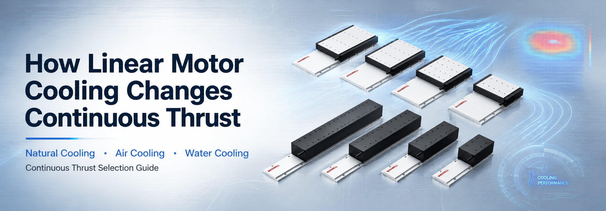
Linear motor cooling changes how much force a direct-drive motor can sustain without excessive winding temperature. It does not remove the electrical, magnetic, mechanical, or servo-drive limits that control short peak output. A more effective heat-removal path allows the winding to carry higher continuous current, but only under clearly defined ambient, mounting, airflow, or coolant conditions.
A practical linear motor cooling decision must consider moving mass, acceleration, cycle time, holding force, installation direction, enclosure temperature, mounting structure, and drive capability together. A peak-force value alone cannot confirm whether an axis will remain thermally stable during repeated production.
Direct answer: Natural cooling usually suits moderate RMS demand and an effective mounting structure. Air cooling can add heat removal without liquid plumbing. Water cooling can support stronger continuous thermal performance, but requires verified flow, inlet temperature, pressure drop, hose routing, leakage control, and condensation prevention. None of these methods provides unlimited peak thrust.
Why Heat Limits Continuous Thrust
A direct-drive linear motor produces force when current passes through its winding inside a magnetic field. Winding resistance converts part of that electrical input into heat. In simplified terms, copper loss rises with the square of current, so a relatively small current increase can create a much larger increase in winding heat.
Continuous thrust is a thermal rating. It describes the force a motor can maintain under stated conditions such as ambient temperature, permitted winding temperature, mounting arrangement, airflow, coolant temperature, and coolant flow. The same motor can reach different steady temperatures when mounted on a broad metal plate or a narrow bracket, or when installed inside a warm enclosed machine rather than a controlled test environment.
Thermal equilibrium occurs when generated heat equals removed heat. If heat enters the motor faster than it leaves, winding temperature continues to rise until protection activates or a permitted component limit is reached. Normal production should keep margin below that boundary because ambient temperature, filter condition, coolant flow, payload, and throughput can change.
Peak Thrust Creates a Different Load
Peak thrust supports short acceleration, deceleration, disturbance recovery, or temporary process-force periods. The winding and surrounding structure absorb heat during the pulse before the complete assembly reaches thermal equilibrium. Peak output cannot continue indefinitely, and repeated high-current pulses can accumulate heat when recovery time is too short.
A requirement such as “high force for one second” remains incomplete without pulse repetition, total cycle time, starting temperature, and the force required during every other phase. One isolated move from a cool start cannot represent a repeated industrial cycle.
RMS Current Connects Motion to Heating
RMS current represents the heating effect of a changing current profile. High-current segments receive more weight because resistive heating follows current squared. A simple arithmetic average can underestimate thermal demand even when it appears to describe the same duty cycle.
Separate acceleration, constant-speed travel, deceleration, settling, processing, holding, and idle time. Assign each segment a current or verified force estimate, weight the squared values by duration, and calculate the square root across the complete cycle.
Simplified RMS relationship: RMS current equals the square root of the sum of each current squared and multiplied by its duration, divided by total cycle time.
Force can support an early estimate when a verified force constant is available, but current is the more direct thermal input. Friction, cable-carrier resistance, guide preload, gravity on vertical axes, control correction, and process disturbances can all increase actual electrical demand. A stationary vertical axis may also draw substantial holding current even though no travel occurs.
The Mounting Structure Is Part of the Heat Path
Thermal resistance describes how strongly a structure opposes heat flow. The complete path can include the winding, encapsulation, mover housing, mounting interface, machine plate, surrounding air, cooling passage, and coolant circuit. A weak connection at any point can restrict the benefit of the remaining components.
A flat, rigid mounting surface can help spread heat while supporting working-gap control. Burrs, debris, thick coatings, gaps, uneven fastener pressure, or a narrow unsupported bracket can reduce conduction. A larger fan or colder coolant cannot fully correct a poor thermal interface.
Temperature also affects the surrounding machine. Expansion of the mounting plate, guide base, encoder support, carriage, tooling, and fixture may influence motion consistency even while the motor remains electrically safe. This deserves attention in a laser motion system, where stable focus position, path geometry, and settling can depend on machine temperature.
Natural, Air and Water Cooling
Natural, air, and water cooling remove heat through different paths. The right method should meet RMS demand with usable thermal margin while avoiding fans, filters, hoses, pumps, fittings, and monitoring equipment that do not improve the real machine objective.
Natural Cooling
Natural cooling uses conduction into the mounting structure, convection into surrounding air, and a smaller amount of thermal radiation. It can suit moderate RMS loads, intermittent operation, controlled enclosure temperatures, and equipment with an effective metal mounting plate. It also avoids moving-air disturbance and liquid-line complexity.
Passive operation still requires planning. Warm air needs a route away from the motor, and covers or narrow enclosures can trap heat. Natural cooling is the first configuration worth evaluating when the cycle contains meaningful low-current intervals and the frame has useful thermal mass, but it should not be selected when calculated RMS demand already approaches the verified continuous limit.
Air Cooling
Air cooling increases convective heat transfer across a surface or through an approved passage. Its result depends on inlet temperature, flow, pressure, direction, and contact with the heated region. A large fan can perform poorly when air bypasses the motor or recirculates warm enclosure air.
Filters protect the cooling path from dust, fibers, and oil mist, but a loaded filter gradually reduces airflow. Compressed-air systems may also need regulation, filtration, and flow verification. Air cooling can suit repetitive motion with medium-to-high thermal demand when a liquid circuit would be excessive, provided airflow does not disturb lightweight workpieces, optical paths, measurement areas, or contamination-sensitive processes.
Water Cooling
Water cooling transfers winding heat into circulating liquid through dedicated passages or an approved cooling structure. It can support higher sustainable current and more stable operating temperature, but the motor becomes part of a circuit that may include a pump or chiller, reservoir, heat exchanger, hoses, fittings, manifolds, and monitoring devices.
Coolant inlet temperature controls the available heat-transfer margin. Liquid that is too cold can bring motor surfaces below the local dew point, creating condensation near electrical connections, encoder components, guides, and precision structures. Stable coolant temperature is usually more useful than the lowest possible temperature.
Flow and pressure drop must be checked at the motor branch, not only at the pump nameplate. Hose length, bends, fittings, valves, and internal passages restrict flow. Parallel branches may require balancing, while series connections deliver warmer coolant to downstream motors. Moving hoses must accommodate full travel without sharp bending, torsion, abrasion, excessive drag, or fatigue.
| Method | Selection and Integration Check |
|---|---|
| Natural | Moderate RMS demand, useful recovery time, stable ambient conditions, effective mounting contact, frame heat spreading, and convection clearance. |
| Air | Repetitive motion needing more heat removal without a liquid circuit; confirm approved airflow path, inlet temperature, filtration, exhaust routing, vibration, and maintenance access. |
| Water | High RMS force, limited recovery time, restricted heat spreading, or tighter thermal stability; confirm inlet temperature, branch flow, pressure drop, condensation, leakage risk, and hose routing. |
How Linear Motor Cooling Changes Sustainable Force
Cooling increases sustainable force by lowering effective thermal resistance between the winding and its heat sink. The winding can carry more RMS current before reaching the same permitted temperature. Within the normal electromagnetic operating range, higher permitted continuous current supports higher continuous thrust.
This improvement comes from thermal management rather than a different magnetic force mechanism. A water-cooled version may sustain more output, but it still has a peak-current limit, force-speed envelope, winding-temperature limit, cable limit, and mechanical installation requirement.
Cooling Does Not Remove Drive and Speed Limits
The servo drive must supply the required continuous and peak current. Available DC bus voltage must also overcome winding resistance, cable voltage drop, inductive demand, and back electromotive force at speed. Stronger cooling cannot restore force once the system reaches a voltage limit.
A motor can remain thermally stable and still lose available thrust near target velocity when the winding and drive combination lacks voltage margin. Review the force-speed curve at acceleration, travel, process, and reversal speeds rather than relying on a single maximum-speed point. Series and parallel winding connections, drive model, bus voltage, and cable length must be considered as one electrical system.
Thermal Derating and Temperature Stability
Thermal derating reduces allowable continuous current when real conditions remove heat less effectively than catalog reference conditions. Higher ambient temperature, a weaker mounting plate, restricted ventilation, a loaded filter, warm coolant, low flow, or contaminated cooling surfaces can all reduce practical capacity.
A catalog rating should not enter a sizing worksheet without its thermal basis. Compare the reference environment with the actual enclosure, mounting method, cooling arrangement, and production cycle. Layout changes such as a new cover, additional servo drive, nearby process heater, or reduced cabinet airflow can require a fresh review even when the motor and motion profile remain unchanged.
Stable temperature can matter more than maximum cooling in precision equipment. Consistent winding resistance and smaller structural temperature changes support repeatable long-term operation. A stable coolant setpoint above the dew-point boundary may be preferable to an unnecessarily cold circuit.
How to Read Cooling Data in a Linear Motor Datasheet
Cooling data only supports selection when it belongs to the exact model and operating condition. Use the complete model designation, winding connection, mover length, and cooling suffix shown in current documentation. Do not combine dimensions from one version with electrical or thermal values from another.
Separate Continuous and Peak Values
Confirm whether force and current values are continuous or peak. Continuous values depend on thermal conditions; peak values require an allowed magnitude and duration. Also check the winding-temperature basis, ambient temperature, mounting surface, permitted sensor response, and whether ratings describe natural, air, or water cooling.
Read Air and Water Conditions as Part of the Rating
An air-cooled value may assume a defined inlet temperature, flow, pressure, and approved passage. A water-cooled value may depend on coolant type, inlet temperature, flow rate, pressure, and maximum permitted temperature rise. Pump operation alone does not prove that each motor branch receives the required flow.
JKB3 data boundary: Current JKB3 documentation may provide separate natural, air, and water-cooled conditions. Use those values only for the exact JKB3 designation and stated operating conditions. Confirm the current datasheet with SAHO before using a cooling value in the final calculation.
WJM, WKM and JKB Selection by Structure and Thermal Demand
WJM and WKM use iron-core structures, while JKB uses an ironless structure. This difference affects force density, magnetic attraction, guide loading, force smoothness, and integration. Cooling determines how much electrical capability can be sustained; it does not remove the structural differences between the motor families.
WJM: Compact Iron-Core Direct Drive
The compact iron core linear motor range balances installation space and force density. Compact layouts may restrict airflow and heat-spreading area, making mounting-plate contact and local enclosure temperature important during repetitive acceleration or extended holding.
Select the exact model from continuous force, peak force, target speed, acceleration, mover and stator length, installation space, and verified heat-dissipation conditions. Because WJM is iron core, guide capacity, frame stiffness, assembly method, magnetic attraction, and working-gap control remain part of the mechanical review.
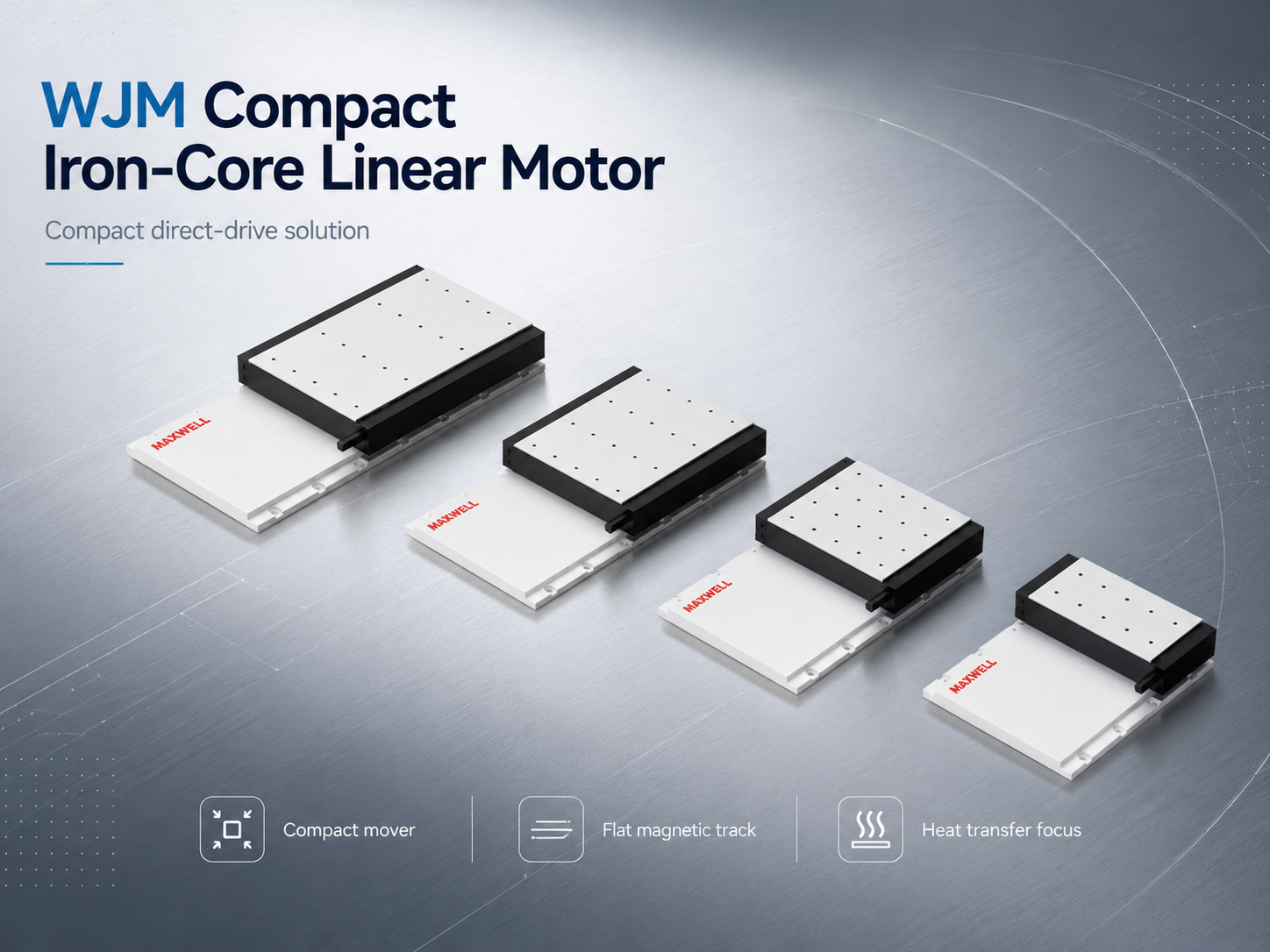
WJM compact iron-core motor family. Final selection requires exact force, working-gap, guide, mounting, and thermal conditions.
View WJM Compact Iron-Core Motors
WKM: Higher-Force Iron-Core Coverage
The high force iron core linear motor range covers more demanding industrial direct-drive loads. Higher force capability can create greater thermal demand when the cycle uses a large share of the continuous range, but a larger motor does not automatically require active cooling when RMS demand remains moderate and the frame removes heat effectively.
Review the exact WKM model, RMS force, magnetic guide loading, drive current, moving mass, frame stiffness, ambient temperature, and model-specific cooling conditions together. Avoid unnecessary oversizing because a heavier mover can increase the demand placed on a lower axis in a stacked system.
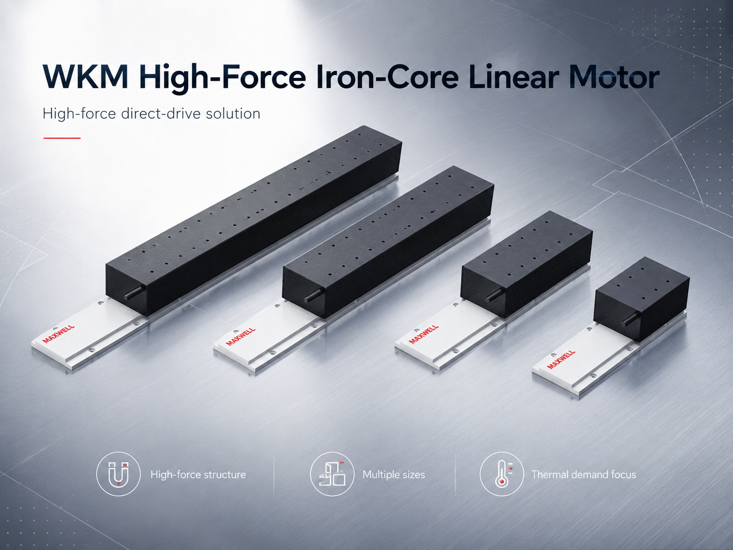
WKM high-force iron-core motor family. Guide loading, frame stiffness, drive current, moving mass, and thermal demand must be reviewed together.
View WKM High-Force Iron-Core Motors
JKB: High-Thrust Ironless Motion
The high thrust ironless linear motor range supports smooth direct-drive motion without iron-core magnetic attraction or cogging. It can be considered where smooth velocity, low vibration, and reduced guide loading matter, but it still requires a rigid support, controlled working gap, encoder feedback, cable routing, and effective heat removal.
Match the exact JKB model to continuous force, peak force, payload, acceleration, mover length, stator length, drive conditions, and documented cooling configuration. Do not extend JKB3 natural, air, or water-cooled values to every JKB model.
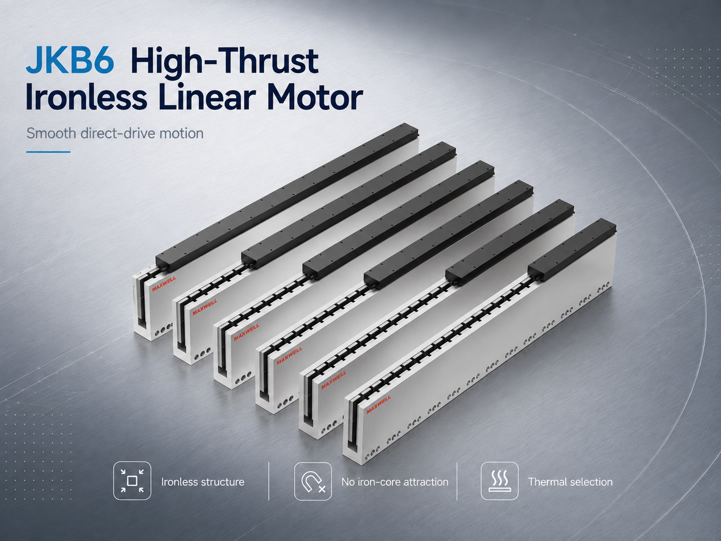
JKB6 high-thrust ironless motor family. Final selection requires the exact continuous force, peak force, drive, mounting, and cooling conditions.
View JKB High-Thrust Ironless Motors
Application Conditions That Change the Cooling Decision
High-acceleration inspection: Peak force may control acceleration, while repetition rate and settling current determine RMS demand. Faster indexing can raise heat even when payload and stroke remain unchanged.
Laser processing and scanning: Repeated path reversals may dominate heating. Temperature stability around the frame and optics can matter as much as maximum motor output, and airflow or hoses must not disturb the optical system.
Semiconductor and measurement equipment: Smooth motion, low vibration, and stable metrology structures may favor an ironless design, but high precision alone does not prove that water cooling is necessary.
Electronic manufacturing: Short repeated moves and reduced idle time can raise RMS current as throughput increases. Validate the planned production rate rather than a slow demonstration cycle.
Vertical axes: Gravity creates holding current while the carriage is stationary. A brake or counterbalance changes the demand but remains separate from thermal protection and power-off safety.
Stacked and multi-axis systems: Upper-axis motors, guides, cables, hoses, and tooling become moving mass for lower axes. Multiple motors in one enclosure also raise the shared ambient temperature.
Cooling Selection Checklist
Define the complete moving mass. Include carriage, fixture, workpiece, tooling, cables, cable carrier, hoses, and upper-axis components.
Record the complete motion sequence. Separate acceleration, travel, deceleration, settling, processing, holding, and idle periods.
Calculate peak and RMS demand. Include inertia, friction, gravity, process force, cable drag, and a controlled engineering margin.
Confirm the real installation. Record direction, local enclosure temperature, mounting-plate contact, frame heat spreading, and available space.
Evaluate the least complex viable cooling method. Compare the calculated RMS requirement with documented natural, air, or water-cooled conditions.
Define the complete active-cooling path. For air, include inlet temperature, flow, filtration, and exhaust. For water, include inlet temperature, branch flow, pressure drop, condensation control, and hose routing.
Check electrical and protection limits. Confirm sensor method, drive current, bus voltage, winding connection, cable length, and the force-speed curve.
Run a steady-state production test. Use the expected payload, production rate, enclosure, and cooling arrangement until motor and frame temperatures stabilize.
Practical rule: Use the least complex cooling method that maintains required RMS output, stable temperature, acceptable thermal drift, and sufficient margin during the real production cycle.
Installation Conditions That Can Reduce Cooling Performance
Mounting and Heat-Path Problems
A narrow bracket may support the motor mechanically but spread heat poorly. Burrs, paint, debris, uneven surfaces, incorrect fastener pressure, and unsuitable interface material can create another bottleneck. The mounting surface must remain flat, clean, rigid, and compatible with working-gap and guide-alignment requirements.
Airflow and Enclosure Problems
Covers can trap hot air even when room temperature is moderate. Fans may move a large volume through the enclosure while little air reaches the approved cooling path, or an inlet may draw warm exhaust back into the motor area. Define the route from cool inlet to warm outlet and include filter condition in preventive maintenance.
Coolant Flow and Condensation Risks
A running pump does not prove flow through each motor branch. Closed valves, air pockets, clogged passages, unbalanced manifolds, and pressure drop can reduce local circulation. Coolant below the dew point can also form moisture on the motor, fittings, hoses, frame, encoder support, and nearby electrical parts.
Motion Routing and Incomplete Testing
Hoses and cables must tolerate repeated movement, bend radius, torsion, abrasion, pressure, and fatigue. Their mass and changing drag belong in the force calculation. Commissioning must reproduce the expected payload, cycle rate, enclosure condition, and cooling setup long enough to reveal the final steady temperature.
Frequently Asked Questions
How does cooling increase continuous thrust?
Cooling lowers effective thermal resistance, allowing the motor to sustain more RMS current before reaching its permitted winding temperature. Higher continuous current supports higher sustainable force within the stated cooling, ambient, mounting, drive, and speed conditions.
When is natural cooling enough?
Natural cooling can be sufficient when RMS current remains comfortably below the verified continuous limit, the mounting plate provides an effective heat path, and enclosure temperature remains controlled. Peak magnitude and duration must also stay within model limits.
When should air or water cooling be considered?
Air cooling is relevant when passive heat removal lacks margin but a liquid circuit would add unnecessary complexity. Water cooling becomes relevant for higher RMS demand, limited recovery time, restricted heat spreading, or tighter temperature stability. Both require an approved model-specific configuration.
Does cooling change peak thrust?
Cooling does not remove the electromagnetic peak-force limit. A cooler winding may provide more transient thermal margin, but permitted peak magnitude, duration, repetition, drive current, and operating speed still come from verified model documentation.
Information Required for Model and Cooling Selection
A useful sizing request describes the complete axis rather than only a motor family or target-force value. Provide enough information to compare peak force, RMS demand, speed, thermal conditions, installation limits, and maintenance requirements together.
Moving load, carriage, fixture, tooling, cables, carrier, hoses, and upper-axis mass
Required stroke, usable travel, speed, acceleration, deceleration, and complete cycle time
Process force, holding force, settling requirement, accuracy, and repeatability
Horizontal, vertical, inclined, or inverted installation and available mounting space
Guide type, preload, stiffness, friction, mounting plate, and machine-frame conditions
Normal and maximum enclosure temperature, dust, humidity, oil mist, vibration, and nearby heat sources
Preferred natural, air, or water cooling and available air or coolant conditions
Temperature monitoring, encoder, servo drive, bus voltage, current, controller, cables, and connectors
Expected future changes in payload, recipe, duty cycle, or production rate
Confirm the Motor and Cooling Configuration
Send SAHO your moving mass, stroke, speed, acceleration, complete duty cycle, installation direction, enclosure temperature, mounting arrangement, available airflow or coolant conditions, servo drive, encoder, and controller information. The engineering team can then narrow the WJM, WKM, or JKB model and determine whether natural heat spreading or a verified active-cooling configuration should be reviewed.
Final Selection Priorities
A reliable cooling decision comes down to three checks:
Calculate peak and RMS demand from every segment of the real production cycle.
Compare the actual installation with the temperature and cooling conditions stated for the exact selected model.
Run an extended commissioning test and confirm stable current, winding temperature, airflow or coolant condition, and motion performance.
The final configuration should maintain required continuous thrust with stable temperature, practical maintenance, and enough margin for normal production changes.