

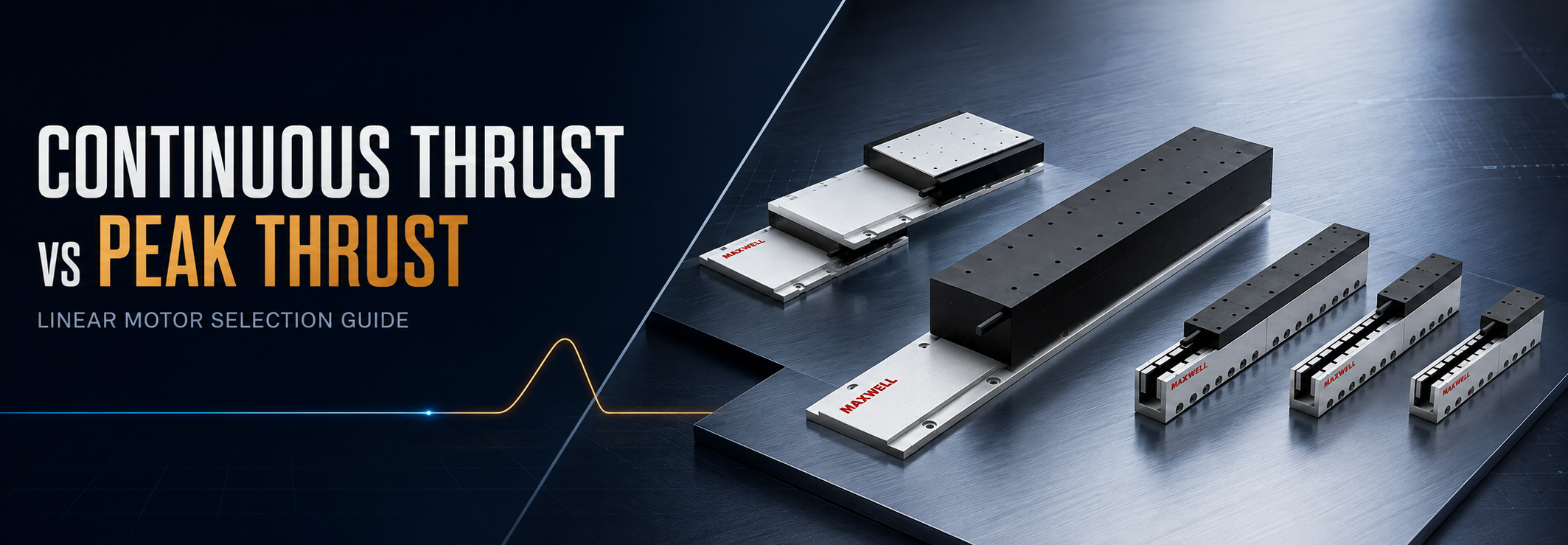
Continuous thrust vs peak thrust describes two different limits that must be checked before a linear motor remains on the shortlist. Continuous thrust answers whether the motor can repeat the production cycle without exceeding its thermal condition. Peak thrust answers whether it can supply a short acceleration, deceleration, reversal, holding correction, or temporary process load.
A high peak value does not prove that a motor can run the machine continuously. Likewise, an acceptable continuous value does not prove that the motor can deliver a demanding acceleration pulse or maintain the required force at operating speed. If either force check fails, reject that configuration. If both pass, keep it only long enough to verify force at speed, drive limits, cooling, and structural fit. Reliable selection needs a force-time profile, not one catalog number.
Core sizing rule: the highest absolute force in any operating segment must stay within the verified peak capability of one exact motor configuration. The complete-cycle RMS force must also stay within the verified continuous capability under the intended mounting, ambient, and cooling conditions.
| Rating | What it protects against | What to compare |
|---|---|---|
| Continuous thrust | Excessive heating during the repeating production cycle. | Complete-cycle RMS force against the continuous rating for the actual thermal condition. |
| Peak thrust | Insufficient transient force during acceleration, braking, reversal, recovery, or a short process event. | Highest absolute segment force, pulse duration, repetition rate, drive current, and force at speed. |
What Continuous Thrust Controls
Continuous thrust is the sustainable force associated with a defined thermal condition. Motor current creates electromagnetic force, but winding resistance also creates heat. During production, that heat must leave through the motor body, mounting interface, machine base, surrounding air, or a cooling method confirmed for the selected model.
This is why a short test can be misleading. The first few moves may run while the motor and base are still cool. If each new cycle starts before the previous heat has left the system, winding temperature continues to rise even though every individual move looks normal.
Continuous demand includes more than constant-speed travel. Acceleration, scanning, process contact, deceleration, settling, return travel, and powered waiting can all require current. A stationary vertical axis may still support gravity, while another axis may hold against cable tension or a process force.
The rating condition matters as much as the number. Mounting-plate contact, enclosure temperature, airflow, nearby process heat, and the approved cooling arrangement affect heat removal. A value established under one condition should not be transferred automatically to a different installation.
What Peak Thrust Controls
Peak thrust is a higher output available for a limited event. It normally appears during acceleration, deceleration, direction reversal, breakaway motion, disturbance recovery, or a short process-force interval. Because the current is higher, force level, pulse duration, and repetition rate must be reviewed together.
For a horizontal axis, the first inertial estimate is total moving mass multiplied by acceleration. Friction, process force, cable drag, hose resistance, and other predictable loads are then added. A vertical axis also includes gravity during upward travel and powered holding.
Basic force logic:
Required force = total moving mass × acceleration + friction + process force + other predictable loads.
Total moving mass should include the carriage, payload, tooling, fixture, brackets, encoder hardware, cable carrier, hoses, covers, and any upper axis carried by the stage. Using payload alone can understate the acceleration force of the finished assembly.
Peak force must also be available at the target speed. As velocity rises, back EMF increases the voltage required from the amplifier. A motor may produce the calculated force near standstill but fail to maintain it at the intended operating point.
How Duty Cycle and RMS Force Work Together
Duty cycle divides production into acceleration, travel, process work, holding, return, waiting, and true rest. One active-time percentage is usually too broad because each segment can require a different force. RMS force provides a more useful thermal measure by weighting each force level by the time for which it acts.
RMS force relationship:
RMS force = square root of [(F1² × t1 + F2² × t2 + ... + Fn² × tn) divided by total cycle time].
| Term | Meaning |
|---|---|
| F1, F2 ... Fn | Motor force during each separate cycle segment. |
| t1, t2 ... tn | Duration of the corresponding force segment. |
| Total cycle time | The full repeating production cycle, including powered dwell and genuine rest. |
Positive and negative forces do not cancel thermally because both directions require current magnitude. A powered dwell must use its actual holding force rather than zero. Only a genuinely unloaded interval can be entered as a zero-force rest segment.
For example, consider a three-second cycle with 800 N for 0.2 seconds during acceleration, 250 N for 1.0 second during process travel, 800 N for 0.2 seconds during deceleration, 120 N for 0.6 seconds of powered holding, and 0 N for 1.0 second of genuine rest. The required peak force is 800 N. The RMS force is approximately 330 N: square root of [(800² × 0.2 + 250² × 1.0 + 800² × 0.2 + 120² × 0.6) divided by 3.0]. A candidate therefore needs verified capability above both values under the relevant pulse, speed, and thermal conditions.
This force-based RMS method is a useful first sizing check when force is proportional to current across the evaluated segments. Final confirmation should use the selected motor and drive data, including force constant, current limits, winding temperature, cooling method, and the manufacturer’s permitted peak duration.
How to Apply Continuous Thrust vs Peak Thrust in Motor Selection
The purpose of calculating force is not simply to fill a worksheet. Each result should remove configurations that cannot satisfy the same machine requirement. The following sequence keeps the decision traceable.
Check peak force first. Remove every configuration whose verified peak force or permitted peak duration is below the highest absolute force segment.
Check complete-cycle RMS force. Remove every remaining configuration whose verified continuous capability is below the RMS demand for the intended thermal condition.
Check force at speed. Remove a configuration when the motor and drive cannot maintain the required force at the operating velocity, even if the low-speed force appears sufficient.
Check the installed structure. Remove a configuration when mover length, stator length, guide capacity, attraction force, heat path, cable routing, or service clearance does not fit the machine.
| Calculation result | What the result means |
|---|---|
| Peak passes, RMS fails | The motor can produce the short force event but is thermally unsuitable for repeated production. Review cycle timing, powered dwell, heat removal, or continuous capability. |
| RMS passes, peak fails | Average heating is acceptable, but acceleration or process-force demand exceeds transient capability. Reduce moving mass or acceleration, or compare another configuration. |
| Both force checks pass, speed fails | Review winding choice, amplifier current, bus voltage, cable length, and the exact force-speed operating point before increasing motor size. |
| Force passes, installation fails | The configuration is still unsuitable. Mechanical envelope, guide loading, magnetic attraction, thermal contact, or cable routing must be revised. |
Four Operating Patterns That Change the Controlling Limit
Short Acceleration Followed by a Long Unloaded Interval
Peak thrust may be the first limit because the motor must deliver a strong acceleration pulse. A long genuine rest can keep RMS demand moderate, but the full calculation still needs to confirm that the repeated pulse remains thermally acceptable.
High-Frequency Indexing With Little Recovery Time
Each move may stay below peak, yet the motor can continue heating because the next move begins quickly. In this pattern, RMS force and continuous capability often control the selection rather than the single highest force value.
Long Scanning or Contour Motion at Elevated Speed
A long scan may require moderate force for an extended period while the axis is already moving quickly. Continuous capability and force at speed both become important. A laser motion system may combine this sustained segment with a separate high-force repositioning move.
Vertical Travel With Powered Holding
Gravity raises the force baseline during upward travel and remains during powered holding. A vertical axis may pass the acceleration peak yet fail the continuous check because holding force occupies a large part of the cycle. Braking and power-off support remain separate safety decisions.
How WJM, WKM, and JKB Should Enter the Shortlist
WJM and WKM belong to SAHO's iron-core motor range, while JKB belongs to the ironless range. They should not be presented as three sizes in one simple ladder. WJM and WKM are mainly compared when the project remains within an iron-core structure. JKB enters when an ironless structure gives the stage a better mechanical or motion-system fit.
WJM: Retain the Compact Iron-Core Direction When One Exact Configuration Passes
A compact iron core linear motor is a practical starting direction when the required force fits a listed WJM configuration and installation space is limited. WJM is not a universal answer for every compact axis; one exact configuration still has to pass peak, RMS, speed, thermal, and installation checks.
The WJM100 page gives a useful model-level example. It lists 145 to 460 N continuous thrust and 384 to 1420 N peak thrust across motor lengths of 56, 96, and 176 mm. These figures belong to separate configurations and cannot be combined freely.
WJM remains on the shortlist when the force results pass and its compact iron-core structure fits the guide, base, and heat path. If force capacity alone is insufficient, WKM becomes the next iron-core comparison. If force is sufficient but normal magnetic attraction or cogging behavior is the concern, an ironless direction should be evaluated instead of moving automatically to WKM.
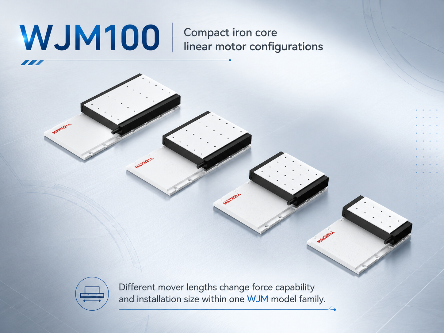
WJM100 configurations illustrate how mover length changes force capability and installation size within one WJM model family.
WKM: Enter a Higher Iron-Core Force Class for a Defined Reason
A high force iron core linear motor should enter the comparison when the suitable WJM configuration cannot provide the required continuous force, peak force, or engineering margin. The reason for changing series should be visible in the calculation rather than based on a general preference for a larger motor.
WKM contains several separate force families. For example, the WKM50 page lists 200 to 1200 N continuous thrust and 440 to 2640 N peak thrust across motor lengths of 112, 196, 364, and 532 mm. Those values describe different configurations within WKM50, not one motor with an adjustable length and force.
Higher available thrust also raises reaction loads in the machine. Guide rigidity, moment loading, mounting stiffness, heat dissipation, amplifier current, bus voltage, and settling behavior require review. WKM only adds value when the mechanical and electrical system can use the higher force effectively.
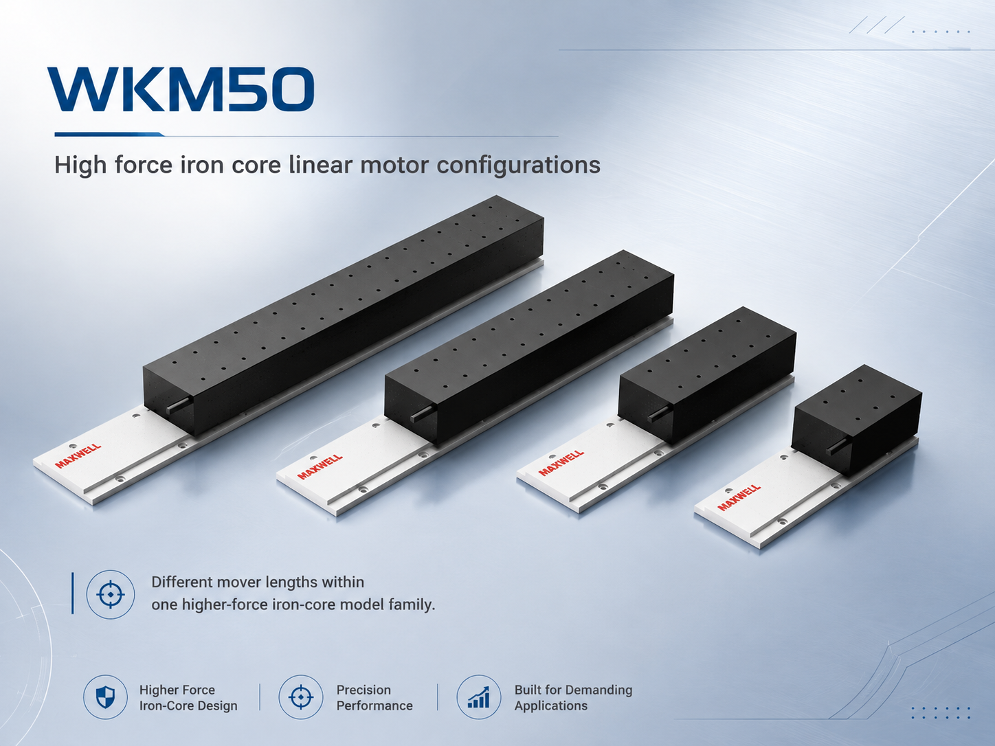
WKM50 configurations illustrate different mover lengths within one higher-force iron-core model family.
JKB: Compare an Ironless Structure, Not Another WKM Size
The high thrust ironless linear motor range should not be presented as the next size above WKM. JKB uses an ironless structure and includes six families from JKB1 through JKB6. Its selection begins with the same force calculation, but the reason for entering the range is structural as well as numerical.
The ironless structure avoids the normal attraction force and cogging mechanism associated with iron-core designs. This can be valuable where guide loading, force smoothness, velocity behavior, or settling sensitivity matters. Final stage accuracy and vibration still depend on the guide, encoder, frame, cables, drive, and servo tuning.
The JKB page demonstrates broad internal coverage rather than one fixed force level. The JKB1 example shown below lists 3 to 14.9 N continuous thrust and 11.9 to 59.9 N peak thrust across five rotor lengths. This data explains configuration changes within JKB1; it is not a direct force-class comparison with WJM100 or WKM50. Higher-force JKB families must be selected separately from the actual force and structure requirements.
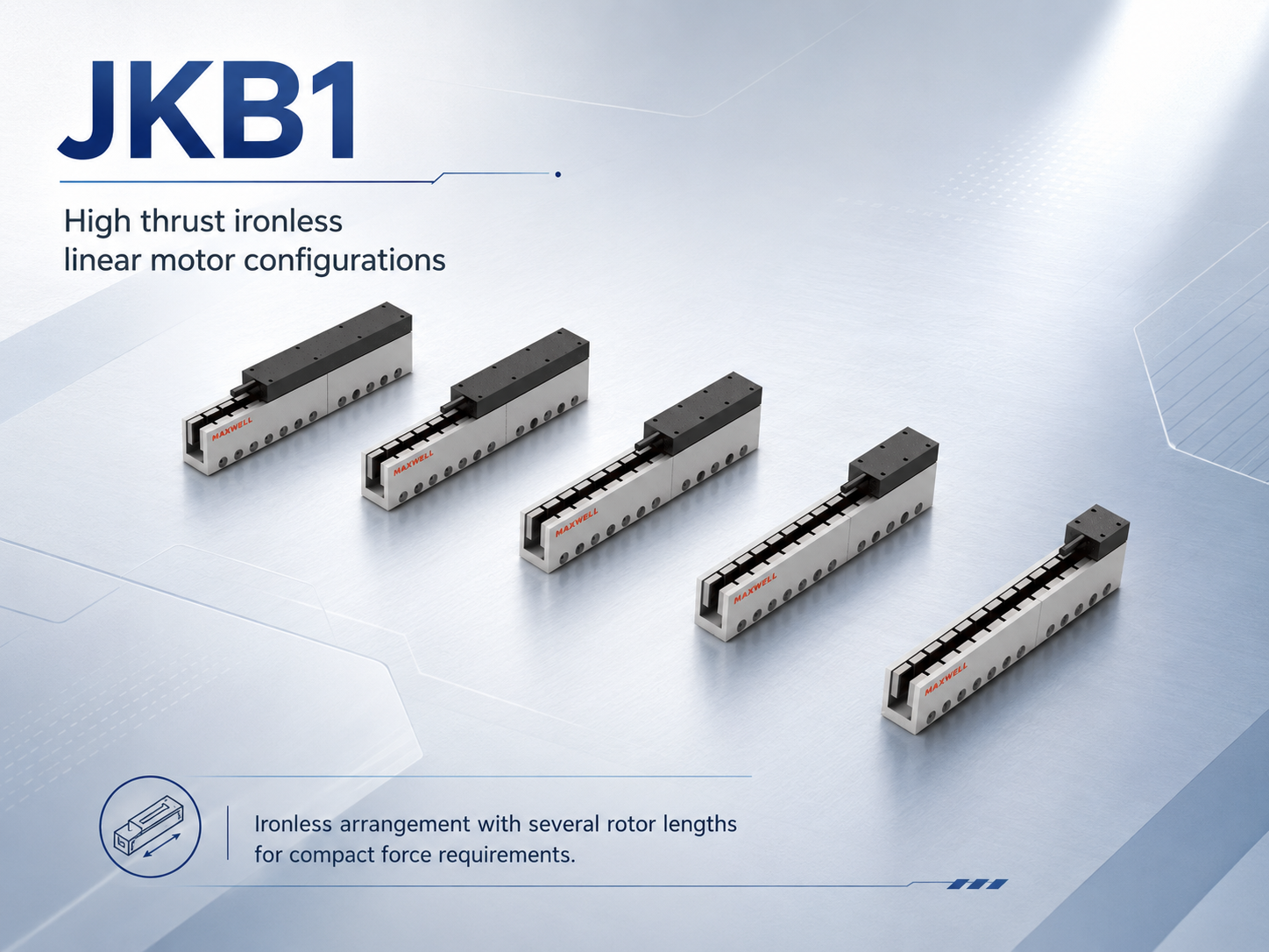
The JKB1 image illustrates the ironless arrangement and several rotor lengths; final JKB selection still begins with the required family and force level.
What to Change When a Candidate Fails
| Failed check | Practical response |
|---|---|
| Peak force is too high | Reduce moving mass or acceleration, measure uncertain external force, or compare a configuration with greater verified peak capability. |
| RMS force is too high | Reduce repetition, shorten powered holding, improve the confirmed thermal path, or select greater continuous capability. |
| Force is unavailable at speed | Review velocity, winding choice, amplifier current, bus voltage, cable length, and the exact force-speed operating point. |
| Iron-core attraction is unsuitable | Recheck guide and base loading. When force demand already passes, compare an ironless JKB direction rather than moving automatically from WJM to WKM. |
| Installation envelope is unsuitable | Review motor length, stator length, mounting contact, cooling access, cable routing, and service clearance before keeping the series. |
A Practical Selection Workflow
List every moving component and calculate total moving mass.
Divide the real production cycle into holding, acceleration, travel, process, deceleration, return, waiting, and true rest.
Calculate force and duration for every segment, including gravity and predictable external loads.
Identify the required peak force and calculate complete-cycle RMS force.
Check force at target speed and confirm the installed thermal condition.
Decide whether the project remains within an iron-core direction or needs an ironless comparison.
Compare one exact WJM, WKM, or JKB configuration rather than combining values from different models.
Record why each candidate was retained or rejected so later payload, speed, or cycle changes can be reviewed.
For broader motion-system planning, the guide on linear axis design for industrial automation helps separate direct-drive requirements from screw and belt priorities. The direct drive linear motor selection guide provides additional system context, while the SAHO linear motor catalog can be used after the force and structure requirements are defined.
Common Selection Mistakes
Selecting from the largest peak figure without calculating RMS force.
Treating every stationary period as zero-force cooling time.
Using a family maximum as the rating of every motor configuration.
Ignoring force at speed, mounting contact, guide loading, or iron-core attraction.
Moving from WJM to WKM or JKB without a calculation or structural reason.
Using a larger motor to compensate for an unmeasured load, flexible frame, or incomplete motion profile.
Frequently Asked Questions
What Is the Difference Between Continuous Thrust and Peak Thrust?
Continuous thrust is the sustainable force under a defined thermal condition. Peak thrust is a higher short-duration force used for acceleration, deceleration, disturbance recovery, or a temporary process load.
Can a Linear Motor Run Continuously at Peak Thrust?
Peak output should not be treated as an unlimited operating point. Current, duration, repetition rate, and thermal effect must stay within the exact model's verified conditions.
How Does Duty Cycle Affect Continuous-Force Selection?
Duty cycle determines how long each force level acts and how much genuine cooling time exists. Segment-based RMS force gives a clearer thermal check than one active-time percentage.
When Should WJM, WKM, or JKB Be Considered?
WJM remains the compact iron-core direction when one exact configuration passes. WKM enters when a higher iron-core force class is required. JKB enters when an ironless structure provides a better system fit than an iron-core motor.
What Information Is Needed for Model Confirmation?
Required information includes moving load and payload, stroke, target speed, acceleration, cycle time and duty cycle, installation direction, process force, accuracy or repeatability, cooling and environment, encoder, controller, servo drive, and available bus voltage.
From Application Data to a Shortlisted Motor Direction
After receiving the application data, SAHO can review the highest-force segment, calculate or verify cycle RMS demand, check force at operating speed, and separate iron-core from ironless requirements. The remaining direction can then be narrowed toward a specific WJM, WKM, or JKB family.
The next step is not simply to name a series. It is to confirm the exact motor or rotor length, stator length, drive current, bus voltage, encoder arrangement, thermal condition, cable path, and installation envelope that match the machine.
Submit the complete motion profile, not only a product name.
Include moving load, stroke, speed, acceleration, cycle time, duty cycle, installation direction, process force, cooling, encoder, controller, and drive information.
If any input is still estimated, submit both the expected value and a credible worst case. Freeze the final model only after one exact WJM, WKM, or JKB configuration passes the peak, RMS, speed, drive, thermal, and installation checks under the same machine requirement.