

A reliable linear motor sizing process begins with the complete moving mass and the real production sequence. The calculation must then separate acceleration force, process force, gravity, friction and cable resistance. After that, peak thrust, RMS force, force at speed, cooling and mechanical structure must all pass before a motor remains on the shortlist.
Payload alone cannot define the motor. A light tool can still require high thrust when acceleration is aggressive, while a heavier axis can remain thermally manageable when the cycle includes genuine recovery time. For that reason, the useful question is not simply how much mass the motor can move. The useful question is what force the complete axis needs during every part of one repeating cycle.
Four gates control the first shortlist: the highest force segment must stay inside verified peak capability; complete-cycle RMS force must stay inside continuous capability; the required force must remain available at operating speed; and the installed guide, frame, cooling and feedback structure must support the selected motor.
Start With Complete Machine Data
The calculation should begin with a controlled application sheet rather than a catalogue page. Missing mass, an unrealistic move time or an undefined cooling condition can shift the result toward the wrong family. Therefore, the input sheet should describe normal production, the heaviest expected state and any faster return movement.
Total moving mass includes more than the workpiece. Tooling, fixture plates, brackets, fasteners, cameras, lights, sensors, cable carriers, pneumatic tubes, covers and the moving motor component all add inertia. On a multi-axis mechanism, the lower axis may also carry complete upper-axis assemblies.
Cable carriers require two separate entries. Their moving mass belongs in the inertia calculation, while their bending resistance belongs in the external-force calculation. In addition, that resistance can change near the centre and ends of travel.
Installation direction changes the force model. A horizontal axis mainly overcomes inertia, guide resistance, cable drag and process force. A vertical axis also carries gravity during movement and may continue producing holding force during a process dwell.
Stroke should describe the complete mechanical requirement. Process travel, homing distance, deceleration space, overtravel protection, sensor clearance and service access may all add length. Consequently, the magnetic-track arrangement often needs more travel coverage than the nominal process move.
Speed and acceleration must be connected to distance and time. A requested top speed may look reasonable until acceleration and braking distances are placed inside the available stroke. Likewise, a short move may never reach the programmed speed, even when the drive command contains that value.
Cycle time must cover the whole production rhythm. Forward acceleration, constant-speed travel, braking, settling, process dwell, return movement and waiting all affect force or heat. Short repeated indexes can be more demanding than one long move because high current returns before the motor has cooled.
Accuracy and repeatability belong on the same input sheet, but they should not be treated as motor-only properties. Encoder installation, rail straightness, base rigidity, thermal growth, tooling deflection and servo tuning all influence the result at the process point. Therefore, the required process performance should be stated together with the motor calculation.
| Required input | What should be recorded |
|---|---|
| Moving mass | Workpiece, tooling, fixture, carriage plate, motor mover, brackets, sensors, covers, cables, hoses and any upper axis carried by the stage. |
| Travel requirement | Process stroke, home position, braking distance, overtravel allowance, sensor space and service clearance. |
| Motion target | Forward and return speed, acceleration, deceleration, move time, settling time and complete cycle time. |
| External force | Guide drag, cable resistance, hose resistance, material tension, contact force, pressing load or another repeatable process disturbance. |
| Installation direction | Horizontal, vertical, inclined, gantry or parallel-motor arrangement, including any counterbalance or holding mechanism. |
| Thermal condition | Ambient temperature, enclosure, mounting contact, available airflow, cooling method and nearby process heat. |
| Motion quality | Required accuracy, repeatability, constant-velocity behaviour, settling time and sensitivity to vibration. |
| Control system | Servo drive, bus voltage, current capability, encoder format, controller platform, Hall sensors and temperature feedback. |
When force density and strong acceleration are already central requirements, a high force iron core linear motor can enter the first comparison. However, WKM should not remain on the list simply because its structure can produce strong thrust. Attraction load, frame stiffness, heat removal and force at speed must still match the machine.
Calculate Acceleration Force and External Load
Acceleration force begins with Newton’s second law. The relationship is simple, but the result is only as accurate as the moving mass and acceleration entered into it. A payload-only value normally understates the force required by the finished axis.
Preliminary required thrust:
Frequired = total moving mass × acceleration + friction + cable drag + process force ± gravity component
For a vertical axis, the gravity component is mg. For an axis inclined by angle θ from horizontal, use mg sin θ and apply a consistent positive or negative direction.
This expression provides a preliminary force estimate, but it does not confirm motor suitability until peak duration, complete-cycle RMS force, force at speed, cooling and structural limits are checked. The inertia term comes from complete moving mass multiplied by acceleration. Friction, cable drag, process force and gravity are included only when they exist in the real machine, so the worksheet stays practical rather than becoming a mathematics exercise.
Add Only the Loads That Exist in the Machine
Every added term should have a defined source. Guide friction may come from preload, seals, wipers, lubrication condition or alignment. Cable resistance may come from the carrier, hoses, tubing or stiff feedback cables.
Process force can dominate a light stage. A dispensing head may carry little mass but maintain contact with a surface. A web-handling axis may fight material tension during constant-speed travel, while a pressing or wiping process may add force only during a short part of the cycle.
Disturbance allowance should not become an unexplained percentage. Vacuum-line movement, fixture contact, hose pressure change or reaction from another axis can create repeatable loads. Those loads should be measured where possible or documented as separate engineering assumptions.
Vertical and Inclined Axis Force
Gravity must be added during upward movement. During controlled downward travel, gravity changes direction relative to the commanded force, but the motor may still need substantial braking output. The drive system may also need to manage returned energy.
A consistent sign convention prevents errors. A negative result does not mean the motor produces no force. Instead, it means the required electromagnetic force acts in the opposite direction.
The angle term can create a meaningful continuous load even when the axis is only slightly inclined. If the machine holds position on that incline, the same gravity component may continue during dwell. A counterbalance changes the force profile and should therefore appear in the application data.
Loaded and Empty Moves Need Separate Rows
The most demanding move is not always the loaded move. A machine may accelerate a loaded fixture gently and return the empty fixture much faster. In that case, the empty return can create the highest peak force even though its mass is lower.
Likewise, the process move may include a contact force that disappears on return. The calculation should therefore contain separate rows for each payload and process state. Combining them into one average load can hide the true controlling segment.
Multi-Axis and Gantry Mass Ownership
On an XY or XYZ mechanism, each axis carries a different portion of the system. The base axis may accelerate complete upper-axis modules, tooling and cables. The upper axis carries only components mounted downstream from its own carriage.
Parallel gantry motors add another layer. Equal commands do not guarantee equal mechanical load when the frame twists or guide alignment differs between sides. Therefore, force sharing, cross-axis stiffness and synchronised control should be reviewed together.
Use the following force-calculation sequence:
List every moving component and record its mass.
Create separate states for loaded travel, process travel and empty return.
Calculate inertial force for each acceleration and deceleration segment.
Add gravity for vertical or inclined installation.
Add measured or justified guide and cable resistance.
Add process force only during the segment where it acts.
Record force direction, segment duration and operating speed.
Carry every segment into the peak and RMS review.
At this stage, the result is a mechanical requirement rather than a final motor selection. A motor may produce the calculated force at low speed but fail at the intended operating velocity. Current limit, bus voltage, winding choice and thermal condition still need confirmation.
Worked Example: Calculate Force by Cycle Segment
Consider a horizontal axis with 42 kg of total moving mass in its loaded state, including the workpiece, tooling, carriage, mover and moving cable mass. The empty-return mass is 36 kg after the workpiece leaves the fixture. Measured guide and cable resistance is 55 N. The process adds 80 N during the forward working move but not during the empty return. These values are an illustrative calculation, not WKM or JKB catalogue ratings.
| Cycle segment | Acceleration | External load | Preliminary motor force |
|---|---|---|---|
| Loaded acceleration | +8 m/s² | 55 N resistance + 80 N process force | 42 × 8 + 55 + 80 = 471 N |
| Process travel at constant speed | 0 m/s² | 55 N resistance + 80 N process force | 0 + 55 + 80 = 135 N |
| Loaded braking | −8 m/s² | Resistance and process force applied using the chosen direction convention | Record the signed result and use its absolute value for the peak check |
| Empty return acceleration | −10 m/s² | 55 N resistance; no process force | −(36 × 10 + 55) = −415 N; calculate it separately because the faster return may control peak force |
Carry every force value into the complete-cycle RMS calculation:
| Cycle segment | Signed motor force | Duration |
|---|---|---|
| Loaded acceleration | 471 N | 0.20 s |
| Process travel | 135 N | 0.60 s |
| Loaded braking | −201 N | 0.20 s |
| Powered process dwell | 80 N | 0.30 s |
| Empty-return acceleration | −415 N | 0.15 s |
| Empty-return travel | −55 N | 0.40 s |
| Empty-return braking | 305 N | 0.15 s |
| Genuine rest | 0 N | 0.20 s |
The 471 N result is not a motor recommendation. Each segment still needs a duration and operating speed. For this 2.20-second example cycle, square each force, multiply it by the corresponding duration, add the results, divide by 2.20 seconds and take the square root. The resulting RMS force is approximately 220 N.
Example elimination result: the preliminary candidate must provide at least 471 N at the speed reached during loaded acceleration, at least 415 N in the opposite direction at the speed reached during empty-return acceleration, and continuous capability above the 220 N RMS result under the intended cooling condition. Engineering margin, peak duration, force-speed limits and the installed structure still need separate confirmation.
For a vertical example, add gravity to upward and holding segments and retain the signed direction during downward travel and braking. The same segment-by-segment method prevents upward travel, powered dwell and regenerative deceleration from being hidden inside one average load.
Build the Motion Profile Before Judging Cycle Time
A motion profile turns the machine sequence into force over time. Without it, peak force and thermal demand remain disconnected. The complete cycle should therefore be divided into acceleration, travel, braking, settling, process, return and genuine rest.
A trapezoidal profile contains acceleration, constant-speed travel and deceleration. It applies when the stroke is long enough for the axis to reach target speed. A short move often creates a triangular profile because acceleration and braking consume the available distance.
The motion profile should confirm whether the target speed can actually occur inside the available stroke. When acceleration and braking consume the full move, no constant-speed segment remains. In that condition, raising the programmed top speed does not shorten the cycle.
S-curve motion limits jerk, which is the rate of acceleration change. A smoother command can reduce shock, cable movement and structural vibration. However, the new profile changes segment duration and may change both peak and RMS force.
Settling time belongs inside the production cycle. A mathematically complete move may still leave the process point vibrating. Inspection, measurement or laser work may therefore begin only after the stage reaches an acceptable stability band.
Process dwell can create thermal demand even when speed is zero. A vertical stage may support gravity, while a contact process may maintain force against the workpiece. Only a genuinely unloaded and unpowered interval should be treated as zero-force cooling time.
| Cycle segment | What should be defined |
|---|---|
| Forward acceleration | Starting speed, ending speed, acceleration, duration, payload state and external force. |
| Constant-speed travel | Travel speed, duration, guide resistance, cable drag and any process force. |
| Braking | Deceleration, stopping time, force direction and regenerated-energy condition. |
| Settling | Time before the process begins and any holding or disturbance-rejection force. |
| Process dwell | Duration, gravity load, contact force and process stability requirement. |
| Return movement | Return payload, speed, acceleration, braking and any changed cable or process load. |
| Wait or rest | Whether the motor is still powered, whether gravity remains and whether genuine cooling time exists. |
Four Operating Patterns Change the Controlling Limit
Short acceleration followed by a long unloaded interval: peak force often controls the first decision because the axis needs one strong pulse. The long rest may keep RMS demand moderate, but the repeated pulse still needs a thermal check.
High-frequency indexing with little recovery time: each move may stay below the peak limit, yet heat can accumulate because the next index begins quickly. In this pattern, continuous capability and RMS force often remove candidates before peak force does.
Long scanning at elevated speed: moderate force may continue for a long period while the axis already moves quickly. Continuous force and force-speed capability become equally important, especially when constant velocity or low disturbance affects the process.
Vertical travel with powered holding: gravity raises the force baseline during upward travel and remains during dwell. A motor may pass the acceleration pulse but fail the thermal check because holding occupies a large part of the cycle.
In automotive automation, a station may combine transfer, inspection, dispensing, fastening or welding support. Each operation creates a different force-time pattern. The station sequence should therefore define the motor calculation instead of a generic cycle-time target.
Cycle-time check: higher acceleration only adds value when travel time is the real bottleneck. When dwell or settling controls the station, lower moving mass, a stiffer frame, a smoother profile or improved control tuning may produce a larger throughput gain than a larger motor.
Use Peak Force and RMS Force as an Elimination Gate
Peak force protects the axis during the most demanding short event. RMS force evaluates heat across the repeating production cycle. A candidate must pass both checks because strong transient output cannot compensate for insufficient continuous capability.
The highest segment may occur during loaded acceleration, empty return, vertical lifting, process contact or emergency braking. Therefore, the heaviest payload does not automatically define peak demand.
Peak duration and repetition rate also matter. A short high-current event that appears once during commissioning is different from the same event repeated continuously in production. The exact motor configuration and drive must support the force level for the required time.
After the highest force segment is identified, RMS force is the next core calculation for the first shortlist. It converts the full repeating cycle into a thermal demand that can be compared with continuous capability.
Complete-cycle RMS force:
FRMS = square root of [(F₁²t₁ + F₂²t₂ + ... + Fₙ²tₙ) divided by total cycle time]
Each force value belongs to one cycle segment, and each time value is the duration of that segment. Squaring force makes high-force events contribute strongly to heating. Positive and negative force do not cancel because both directions require current magnitude.
Compare the RMS result only with continuous capability verified for the same motor configuration, mounting, ambient temperature and cooling condition. A catalogue value based on a different heat-removal condition is not a direct pass/fail reference.
A powered dwell must use its real holding force rather than zero. Constant-speed travel may also require force because guide drag, cable resistance, material tension or process contact remains. Only a true unloaded rest belongs in the RMS table as zero force.
Force at Speed Is a Separate Check
Passing peak and RMS force at low speed does not prove that the operating point is available at maximum velocity. As speed rises, back electromotive force increases the voltage required from the amplifier. A motor can therefore meet the force calculation near standstill and fail later in the move.
Every critical segment should be paired with operating speed. During acceleration, speed changes throughout the segment, so the required force should remain inside the permitted force-speed region from start to finish. Winding selection, amplifier current, bus voltage and cable length all influence that result.
| Calculation result | What the result means |
|---|---|
| Peak passes, RMS fails | The motor can produce the short force event but cannot repeat the full cycle under the planned thermal condition. Review continuous capability, cycle timing, powered dwell or heat removal. |
| RMS passes, peak fails | Average heating is acceptable, but one acceleration, braking or process segment exceeds transient capability. Reduce mass or acceleration, or compare another exact configuration. |
| Both force checks pass, speed fails | The selected motor and drive cannot maintain the required force at the operating velocity. Review winding, bus voltage, amplifier current and the exact operating point. |
| Force passes, installation fails | The configuration remains unsuitable because guide loading, attraction, motor length, track length, heat path, cable routing or service clearance does not fit the machine. |
This elimination process prevents a common selection error. A motor should not remain on the list simply because one catalogue force value looks high enough. Peak, RMS, speed and installed structure must describe the same exact configuration.
For a deeper explanation of how these two force ratings control selection, see continuous thrust vs peak thrust in linear motor selection.
Choose WKM or JKB for a Structural Reason
WKM and JKB should not be presented as two sizes in one ladder. WKM is an iron-core option, while JKB is an ironless option. The calculation determines whether both can meet force demand, but machine structure and motion behaviour determine which option fits better.
WKM: Higher Iron-Core Force Density
WKM should enter the shortlist when strong force density, demanding acceleration or meaningful process load drives the axis design. The iron-core structure supports a compact high-force configuration, which can be useful when machine space is limited and the motion profile contains high transient demand.
However, the magnetic core creates normal attraction between the mover and magnetic track. That force does not create useful travel, yet the guide and frame must carry it continuously. Rail capacity, bearing life, mounting stiffness and air-gap control therefore become part of the motor decision.
Iron-core structure can also introduce cogging behaviour. Final low-speed smoothness, settling and vibration depend on motor geometry, feedback, guide quality, structural rigidity and servo tuning. Consequently, WKM should be evaluated as one part of the stage rather than an isolated thrust source.
Typical reasons for keeping WKM on the list include heavy moving tooling, high acceleration, repeated strong braking, compact force density and process disturbance that remains too large for a smaller iron-core configuration. The exact family and mover length must still pass the RMS and force-speed checks.
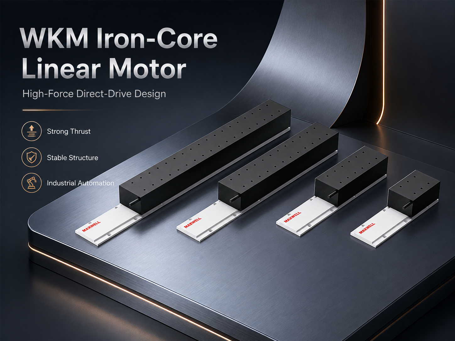
WKM iron-core linear motor and magnetic track for high-force direct-drive axis design.
JKB: High-Thrust Ironless Motion
The high thrust ironless linear motor option should enter the comparison when smooth cog-free force, low magnetic loading and sensitive motion quality matter together with thrust. The ironless structure changes the mechanical relationship between motor, guide and magnetic channel.
Without an iron core in the coil assembly, normal attraction and the usual cogging mechanism are avoided. This can support inspection, optical alignment, scanning, precision positioning and other stages that are sensitive to velocity ripple or settling. Even so, the complete stage still depends on guide straightness, frame stiffness, encoder mounting, cable control and servo tuning.
Ironless structure does not remove thermal limits. RMS force, cooling access, ambient temperature and coil support still need careful review. A motor can provide smooth force behaviour and still become unsuitable when repeated cycle demand exceeds continuous capability.
JKB should therefore remain on the list for a structural reason, not simply because it is another product family. It becomes relevant when the project needs an ironless high-thrust configuration and the magnetic-channel envelope, mover support, drive and cooling arrangement fit the machine.
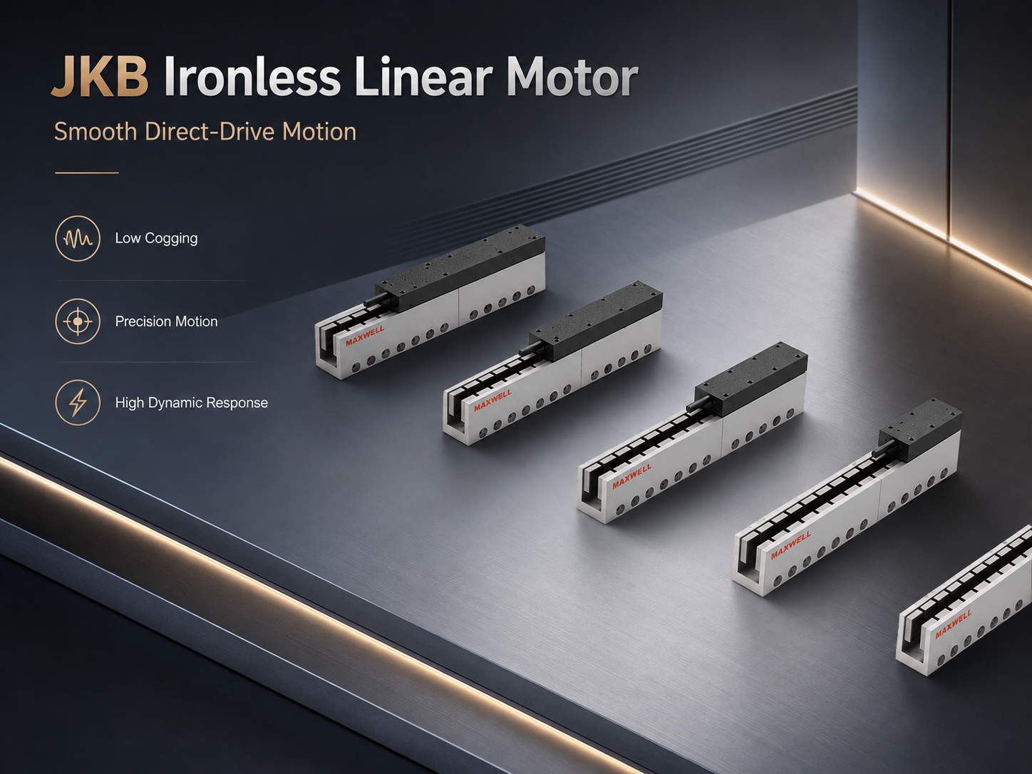
JKB ironless linear motor coil and magnetic track for smooth direct-drive motion.
Where WJM and JKA Fit
WJM and WKM both belong to SAHO’s iron-core range, but they should not be treated as interchangeable labels. WJM can remain the compact iron-core option when one exact configuration passes the force, thermal, speed and installation checks. WKM enters when the calculation and engineering margin require a higher-force iron-core configuration.
JKA and JKB both belong to the ironless range. JKB is the high-thrust ironless target of this guide, while JKA remains a separate family that must be checked against its own verified range and envelope. Values from JKA and JKB should never be combined into one imaginary motor.
| Selection factor | WKM option | JKB option |
|---|---|---|
| Motor structure | Iron-core direct drive | Ironless direct drive |
| Main reason to compare | High force density, strong acceleration and compact thrust structure | Smooth cog-free force, reduced magnetic guide loading and precision dynamics |
| Magnetic attraction | Must be included in guide, bearing and frame calculations | Normal iron-core attraction is not present |
| Motion focus | Strong dynamic output with careful stiffness and cogging review | Smooth velocity, low disturbance and sensitive settling behaviour |
| Mechanical priority | Attraction load, rail capacity, base rigidity and air-gap control | Coil support, magnetic-channel clearance, cable control and guide quality |
| Thermal priority | Continuous output under the planned heat path and cooling method | Coil temperature, RMS demand and available cooling access |
| Typical stage priority | Heavy tooling, force-intensive motion and demanding acceleration | Inspection, scanning, optical positioning and low-vibration motion |
The preferred structure is the one that passes the complete axis review. Motor force, guide loading, frame stiffness, feedback, cooling, drive and cable routing should all describe the same final machine. Moving from WKM to JKB, or from JKB to WKM, without a structural reason only replaces one catalogue name with another.
If the structural difference still controls the decision after the force checks, compare the two motor types in more detail in the guide to ironless vs iron-core linear motors. Use that comparison after the calculated force, RMS, speed and structural requirements have narrowed the technically valid candidates.
What to Change When a Candidate Fails
A failed check does not always mean that the next larger motor is the correct response. Sometimes the motion profile is unrealistic, the moving structure is too heavy or the thermal path is incomplete. The failed result should therefore point to a specific design action.
| Failed check | Practical response |
|---|---|
| Peak force is too high | Reduce moving mass or acceleration, measure uncertain process force, lengthen the move time or compare a configuration with greater verified transient capability. |
| RMS force is too high | Reduce repetition, shorten powered holding, create genuine rest, improve the confirmed heat path or select greater continuous capability. |
| Force is unavailable at speed | Review winding, amplifier current, bus voltage, cable length, target velocity and the exact force-speed operating point before increasing motor size. |
| Settling time is too long | Review jerk, frame rigidity, tooling overhang, encoder location, cable movement and servo tuning rather than relying only on more thrust. |
| Iron-core attraction is unsuitable | Recheck rail and base loading. When force demand already passes, compare an ironless JKB option instead of moving automatically to a larger iron-core motor. |
| Installation envelope is unsuitable | Review mover length, track length, mounting contact, cable exits, cooling access and service clearance before retaining the family. |
| Vertical holding is too demanding | Review counterbalance, brake, process sequence and powered dwell. Do not treat peak motor output as the only vertical-axis safety measure. |
This diagnostic approach improves both engineering and procurement decisions. Each retained configuration has a visible reason, and each rejected configuration has a documented failure. Later changes to payload, cycle time or tooling can then be reviewed without restarting from a product name.
Apply Safety Margins Without Hiding Design Problems
A safety factor should protect against uncertainty, not replace missing data. One universal percentage cannot represent payload variation, friction growth, cooling uncertainty, process disturbance and frame deflection at the same time. Peak, thermal, mechanical and electrical margins should be reviewed separately.
Peak-Force Margin
Peak margin covers short disturbances and uncertainty in acceleration force. Payload variation, changing cable stiffness, process contact and friction growth may all raise the highest force segment. The selected allowance should reflect the quality of measured data and the consequence of exceeding the limit.
Excessive oversizing can create new problems. A larger mover may raise total moving mass, while a larger iron-core structure may increase attraction and guide loading. More catalogue thrust is not useful when the mechanical system cannot apply it cleanly.
Thermal Margin
Thermal margin covers ambient temperature, enclosure heat, production variation and cooling performance. A validated machine with controlled heat removal can use a more precise thermal model. A concept with uncertain airflow or coolant conditions needs greater reserve and stronger temperature monitoring.
Cooling failure also needs a response plan. Blocked filters, reduced airflow, warmer coolant or pump degradation can lower continuous capability. Temperature feedback and controller limits should therefore support safe reduction or shutdown.
When natural, air or water cooling changes the available continuous rating, review the dedicated guide to linear motor cooling and continuous thrust before approving the final configuration.
Mechanical Margin
The guide carries payload, tooling moments, cable force, process disturbance, braking reaction and magnetic attraction where present. Static load, dynamic load and bearing life should all use the complete mechanical case.
Tooling offset can control the design even when total mass is modest. A process head mounted far from the rail centre creates pitch, yaw or roll moment. Rapid acceleration magnifies that moment and can increase vibration or carriage loading.
Frame stiffness connects the force calculation to process accuracy. A high-resolution encoder cannot correct flexible movement outside the feedback loop. The location of the scale, tool and workpiece should therefore be considered together.
Vertical-Axis and Braking Margin
Vertical movement needs a separate power-loss review. Gravity can move the stage after electrical power disappears unless a brake, counterbalance, lock or mechanical stop prevents uncontrolled travel. The motor should not serve as the only safety device.
Deceleration and downward travel can return energy to the drive. Bus capacity, braking resistance, shared DC bus design or regenerative hardware may therefore require confirmation. The result depends on mass, speed, deceleration and cycle frequency.
Environment and Cable Margin
Cable carriers that behave well during slow commissioning may whip or pull during production acceleration. Feedback cables can also add vibration or intermittent signal problems when bend radius and support are poor. Final routing should be tested at production speed.
Dust, oil mist, particles and loose ferrous material affect the axis around the motor. Ferrous debris can be attracted toward exposed magnetic tracks. Guarding, assembly cleanliness and maintenance procedures should therefore match the real environment.
Margin rule: every allowance should have a reason, an owner and a validation method. A larger motor should not be used to hide an unmeasured force, a flexible frame, an incomplete cycle or an undefined cooling path.
Turn the Calculation Into a Shortlist
After peak, RMS and force-speed checks are complete, model comparison becomes more disciplined. The goal is not to choose the largest available configuration. The goal is to retain the smallest practical configuration that passes every operating and integration condition.
Remove force failures. Eliminate any configuration that cannot meet the highest required force at the speed where that force occurs.
Remove thermal failures. Eliminate any configuration whose continuous capability is below complete-cycle RMS demand under the planned cooling condition.
Update moving mass. Add the selected mover or coil mass and repeat the force calculation when the candidate changes axis inertia.
Check physical travel. Confirm motor length, magnetic-track length, overlap, cable exit, cooling access and service space.
Check the guide and frame. Include payload, moments, braking reaction and iron-core attraction where applicable.
Check feedback and drive. Confirm current, voltage, encoder format, controller interface, temperature sensing and regeneration.
Document the reason. Record why WKM or JKB remains so later machine changes can be reviewed efficiently.
A shortlist should contain more than one technically valid option when possible. One configuration may provide greater thermal reserve, while another may reduce moving mass, guide loading or installation space. That comparison supports a complete-axis decision rather than a single product preference.
Direct drive should also be compared with alternative motion structures when the application is still open. A linear motor adds value when fast response, smooth motion, reduced transmission wear or direct force control supports the process. A screw or belt axis may remain more practical for another combination of stroke, load, holding and cost.
The guide on linear motion solutions for industrial automation provides broader context for separating direct-drive, screw-driven and belt-driven requirements before the final axis structure is fixed.
Preliminary Sizing Worksheet
A practical worksheet should contain measured values wherever possible. When measurement is not available, the assumption and its uncertainty should be written beside the value. This keeps the selection traceable and makes later design changes easier to evaluate.
| Worksheet item | Required entry |
|---|---|
| Axis function | Transfer, inspection, scanning, positioning, dispensing, processing or another defined motion task. |
| Installation direction | Horizontal, vertical, inclined, gantry or parallel-axis arrangement. |
| Moving mass breakdown | Workpiece, tooling, fixture, carriage, mover, cables, hoses, covers and upper-axis mass. |
| Stroke and travel allowance | Process stroke, home, braking, overtravel, sensor space and service clearance. |
| Forward profile | Distance, speed, acceleration, deceleration, move time, payload and process force. |
| Return profile | Distance, speed, acceleration, deceleration, payload state and resistance. |
| Dwell and settling | Process duration, holding force, stability band and time before the next command. |
| Force results | Force by segment, highest absolute force, complete-cycle RMS force and force-speed operating points. |
| Thermal condition | Ambient temperature, mounting contact, cooling method, enclosure heat and operating hours. |
| Mechanical condition | Guide capacity, moment load, frame stiffness, attraction load, air gap and cable routing. |
| Control information | Drive, controller, bus voltage, encoder, sensor interfaces and regenerated-energy plan. |
Final Engineering Checks
All moving hardware is included in total moving mass.
Cable mass and cable drag are recorded separately.
Loaded, unloaded and process-contact states use separate force values.
Gravity remains in vertical or inclined dwell segments.
Peak force is checked with duration and operating speed.
RMS force covers the complete repeating production cycle.
Continuous capability matches the intended cooling condition.
The mover mass is fed back into the force calculation.
Guide loading includes tooling moments and attraction where applicable.
Frame stiffness and encoder location support the process requirement.
Drive current and bus voltage support every critical force-speed point.
Vertical power-loss behaviour and regenerated energy are controlled.
Cooling, cables, sensors and motor components remain serviceable.
Known future tooling or recipe changes are included in the margin review.
Frequently Asked Questions
How Do I Calculate the Thrust Required for a Linear Motor?
Start with complete moving mass multiplied by acceleration. Then add guide friction, cable resistance, process force, gravity and other predictable disturbances. Vertical and inclined axes need the gravity component in the correct direction.
Next, calculate force for every motion and dwell segment. The largest absolute value becomes the preliminary peak requirement. The full force-time sequence then supports the RMS calculation.
Finally, pair each critical force with operating speed. Drive voltage, current, winding and cooling can limit usable thrust even when the mechanical equation appears acceptable.
Should Cable Chain and Tooling Weight Be Included in Payload?
Every moving item should appear in total moving mass. Tooling, brackets, carriage plates, sensors, hoses, covers and the motor component all add inertia. Small items can become significant when acceleration is high.
Cable carriers need both a mass value and a drag-force value. Their bending resistance may also change across travel. Measured carrier force gives a stronger result than one general estimate.
How Does Cycle Time Affect Motor Selection?
Cycle time controls how often high-force events repeat and how much genuine cooling time remains. Shorter cycles usually raise RMS demand because acceleration and braking return more frequently. The exact effect depends on both force level and segment duration.
A long dwell does not always reduce heat. A vertical stage may support gravity, and a process stage may maintain contact force while stopped. Therefore, the complete force-time cycle is more useful than a simple moves-per-minute value.
When Should WKM Be Compared With JKB?
Compare WKM and JKB after both structures have been checked against required force and speed. WKM becomes relevant when high iron-core force density and strong dynamic thrust suit the machine. JKB becomes relevant when a high-thrust ironless structure provides a better fit for guide loading, smooth motion or settling sensitivity.
The decision should then compare attraction, cogging behaviour, moving mass, cooling, magnetic-channel envelope, frame stiffness, feedback and drive requirements. Neither family should be selected from product name alone.
What Safety Margin Should Be Reviewed Before Final Selection?
Peak-force margin should reflect payload and disturbance uncertainty. Thermal margin should reflect ambient temperature, cooling performance, enclosure heat and production variation. Mechanical margin should cover guide loading, moments, frame deflection, attraction and braking reaction.
Electrical margin should cover current, voltage, regeneration and feedback integrity. Each margin should have a clear reason and a planned validation method. One unexplained oversizing percentage is not a substitute for those checks.
What Information Is Needed for Final Model Confirmation?
The application package should include moving mass and payload, tooling, stroke, target speed, acceleration, complete cycle time, duty pattern, process force, installation direction and required accuracy or repeatability. Cooling, ambient environment, encoder, controller, servo drive and available bus voltage should also be included.
A complete motion profile is more useful than a request for one product family. It allows the engineering review to verify the controlling force segment, complete-cycle heating, force at speed and mechanical integration before narrowing the selection.
Move From Calculation to a Confirmed Motor Configuration
A preliminary result becomes useful only when it can remove unsuitable configurations. The final review should identify the highest-force segment, calculate complete-cycle RMS demand, verify force at operating speed and confirm whether an iron-core or ironless structure better fits the machine.
The next step is not simply to name WKM or JKB. The exact mover or coil arrangement, magnetic-track length, drive current, bus voltage, encoder layout, cooling condition, cable path and installation envelope must describe one consistent axis.
Submit the complete operating profile.
Include moving load, payload, tooling, stroke, target speed, acceleration, cycle time, duty pattern, process force, required accuracy or repeatability, installation direction, cooling, environment, encoder, controller and servo-drive information.
Send Your Motion Profile for Model Review
When mass, motion profile, peak demand, RMS heating, speed, cooling and structural fit are reviewed together, the final shortlist remains tied to the real machine. That approach reduces oversizing, prevents thermal surprises and gives the engineering team a clear basis for comparing WKM and JKB.