
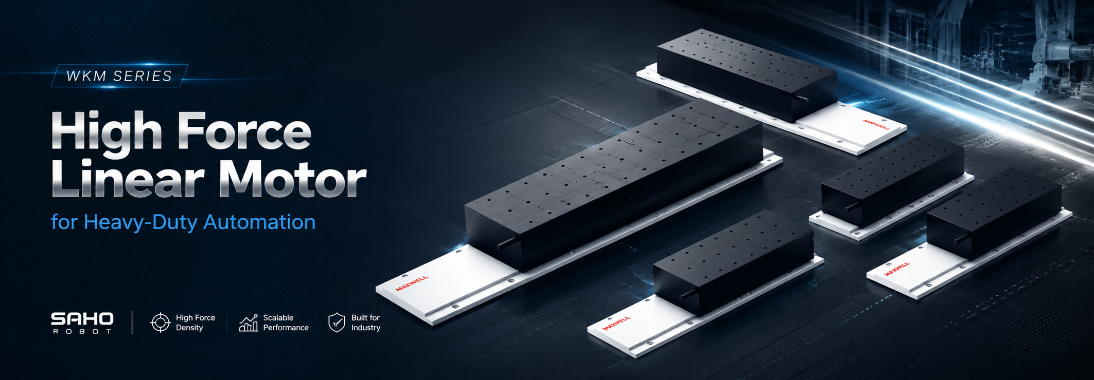
The WKM Series is designed for direct-drive axes that need greater force density, industrial moving loads, rapid acceleration, and controlled thermal performance. A high force linear motor becomes relevant when the motion requirement combines substantial inertia, short cycle times, sustained force, and a machine structure capable of carrying the reaction load. In that situation, selecting by maximum thrust alone gives an incomplete answer.
The more useful task is to determine whether WKM fits the complete motion profile. Moving mass, process resistance, acceleration, duty cycle, guide rigidity, encoder feedback, cooling, and frame stiffness all affect the result. SAHO's high force iron core linear motor range provides several force classes, but the correct model should follow the real machine requirement rather than the largest available specification.
Product scope: WKM provides the iron-core mover and stator components. A complete axis still requires suitable guideways, a carriage and machine structure, encoder feedback, a servo drive, a controller, cable management, and any required thermal system.
What Heavy-Duty Means in a Direct Drive System
Heavy-duty motion is not defined by workpiece weight alone. A moderate carriage can become demanding when the axis accelerates hard, reverses frequently, and has little idle time between moves. A heavier carriage may create a less severe dynamic problem when acceleration remains low and the process includes long dwell periods.
A practical definition combines total moving mass, acceleration, process force, repeated duty, and thermal load. Those variables describe what the motor experiences during production. They also explain why two axes with similar payload figures can need very different WKM configurations.
Start with everything that moves
Payload often refers only to the product, tray, or fixture. The motor may also move a tooling plate, process head, guide carriages, brackets, sensors, protective covers, cable carrier, electrical cables, air tubes, vacuum lines, coolant hoses, and another motion axis. Every component that accelerates with the carriage belongs in the moving-mass figure.
Machine geometry matters at the same time. A laser head, camera bridge, or assembly tool mounted far above the guide plane creates pitch and roll moments. The total mass may look acceptable while the guide layout or carriage structure remains too flexible for the desired acceleration.
Stacked motion systems need another check. On an XY or XYZ machine, the lower axis often carries much of the upper-axis structure. Early sizing based only on product payload can understate the real moving load.
Center-of-gravity position should also be considered before final motor selection. A compact load close to the guide behaves differently from the same mass placed on a tall offset bracket. The motor sees similar inertia, but the guide and frame see a different moment load.
Acceleration can dominate the force requirement
The basic inertial relationship remains the most useful first calculation. Acceleration force equals total moving mass multiplied by required acceleration. Raising either value increases the dynamic force demand directly.
Basic sizing check: acceleration force = total moving mass × acceleration. Add process force, friction, service drag, gravity, and a justified engineering margin separately. Use the resulting force for each motion segment when checking peak and RMS demand.
A 40 kg moving assembly at 10 m/s² requires 400 N only to create the acceleration. That figure does not yet include guide friction, cable resistance, process load, or gravity. The example is simple, but it shows why acceleration can change the motor requirement as strongly as payload.
This first calculation does not confirm a final motor configuration. The completed force-time profile should be checked against peak thrust, RMS or sustained force, and the available thermal margin. The servo drive must also supply the required current and voltage at the target speed, because a configuration that meets a static force figure may still be unsuitable at the intended operating velocity.
Short-stroke machines can be especially demanding. The axis may spend most of the useful movement accelerating and decelerating instead of travelling at a steady speed. In such cases, headline maximum velocity provides limited information about real motor demand.
Jerk also matters because an abrupt change in acceleration can excite tooling or gantry vibration. The force calculation may remain valid while the actual production cycle becomes slower because the machine needs more time to settle.
Keep process force separate from inertia
Many industrial axes do more than move a carriage between two coordinates. Laser systems can add extraction-hose drag and process-head services. Inspection systems may see changing cable resistance, while assembly equipment can encounter probing, pressing, clamping, or contact forces.
These loads should remain visible instead of disappearing inside a large general safety factor. Separating them makes the sizing logic easier to review. It also helps explain measured drive current later if the production machine behaves differently from the early estimate.
Acceleration and deceleration force from total moving mass
External process force acting along the travel direction
Guide friction, seals, and mechanical resistance
Cable-carrier, hose, vacuum-line, and coolant-line drag
Gravity component on vertical or inclined motion
Known variation between normal and maximum operating conditions
Load direction can change across the stroke. A hose bundle may resist motion more strongly near one end, while a process force may act only during a specific section of travel. Both directions and all significant process states should be reviewed.
Repeated production duty separates dynamic force from sustained force
A motor that completes one demonstration move is not automatically suitable for continuous production. Heat develops over repeated acceleration, process, return, and idle periods. The full production cycle is more informative than a single successful move.
A useful profile shows acceleration time, constant-speed travel, deceleration, settling, process dwell, return motion, and the pause before the next cycle. This reveals both the high-force sections and the available recovery periods.
Peak thrust mainly supports short dynamic events. Continuous thrust addresses sustained output and thermal loading. A motor can pass the peak-force calculation and still operate too close to its continuous thermal limit during a high-duty production cycle.
Oversizing creates a different problem. A much larger motor can add moving mass, magnetic attraction, installation volume, drive demand, and structural load. Reserve should cover known uncertainty or process variation rather than replace a complete calculation.
WKM Thrust Range and Model Comparison
WKM is a family rather than one fixed motor size. The current range includes WKM30, WKM50, WKM100, WKM150, and WKM200. Different mover configurations extend the available force within each frame class.
That gives the series a broad engineering span. Smaller WKM frames can fit medium-force industrial axes with aggressive acceleration, while the upper families move into large direct-drive systems where machine rigidity and thermal management become equally important.
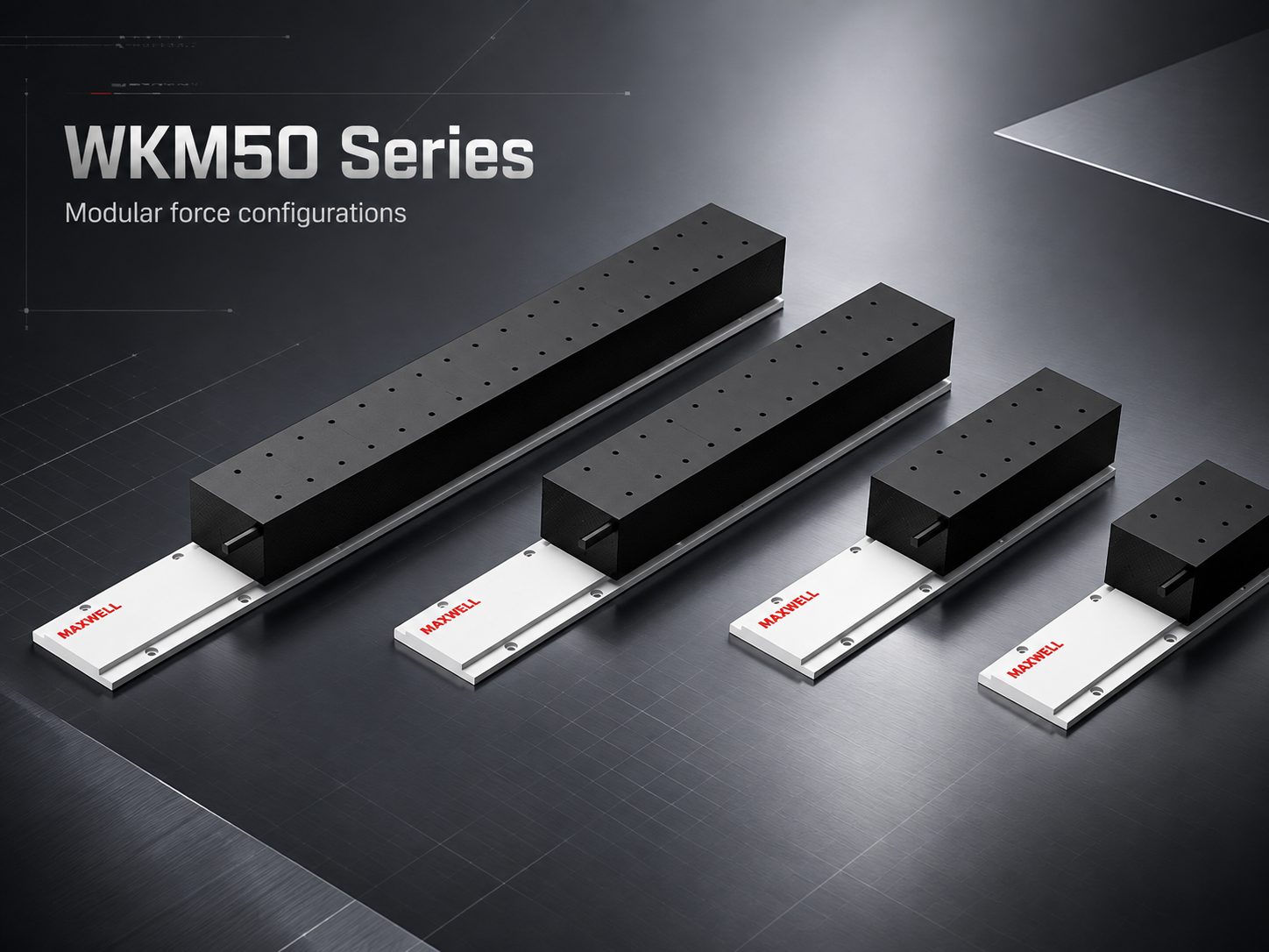
WKM50 product configurations show how different mover sizes can cover different force requirements within one frame family.
| WKM Family | Continuous Thrust | Peak Thrust |
|---|---|---|
| WKM30 | 120–480 N | 266–1065 N |
| WKM50 | 200–1200 N | 440–2640 N |
| WKM100 | 400–1600 N | 880–3520 N |
| WKM150 | 1600–4080 N | 3520–10200 N |
| WKM200 | 2539–4817 N | 6442–12884 N |
How to read the table: each minimum-to-maximum range covers different mover configurations within that WKM family; it is not an adjustable force range for one fixed motor. Confirm the exact configuration, cooling condition, drive requirement, and current datasheet before final selection.
Use peak thrust for the hardest short event
Peak thrust matters during rapid acceleration, deceleration, short process-force events, and disturbance rejection. It answers whether the motor can handle the most demanding brief section of the motion profile.
An indexing axis may demand strong thrust for a fraction of each cycle and then remain lightly loaded during a long inspection or assembly dwell. In that type of system, peak capability can dominate the first model comparison.
Peak force should not be treated as a continuous target. Event duration, repetition rate, mounting, and heat dissipation still need review. A large peak value by itself cannot describe production capability.
Use continuous thrust to check production duty
Continuous thrust becomes more important as machine utilization rises. An axis that moves frequently, carries sustained process load, or has little idle time may become thermally limited without ever approaching its maximum short-duration force.
A useful selection method uses three checks. Peak thrust covers the hardest short event. RMS or sustained force checks the repeated production profile against continuous thermal capability. Force at the required speed confirms that the selected motor-and-drive combination can provide the demand at the real operating point.
A configuration can pass one check and fail the other. For example, the motor may have ample force for acceleration but insufficient thermal margin for a nearly continuous process move.
Selection rule: move to a larger WKM frame when the force-time profile, continuous thermal requirement, available installation envelope, or structural condition justifies it. Extra thrust without a defined purpose can increase integration burden instead of improving the axis.
WKM30, WKM50 and WKM100: where force still meets a compact machine layout
WKM30 and WKM50 can fit systems where the machine remains relatively compact but acceleration or sustained force is already beyond a lighter direct-drive requirement. These frame classes can enter industrial tooling, inspection bridges, scanning heads, and compact production axes when the calculated force supports them.
WKM100 moves the design further toward larger carriages and higher dynamic demand. At that point, guide spacing, tooling overhang, support-plate stiffness, drive capacity, and service routing deserve greater attention.
The important boundary is not simply “small machine” versus “large machine.” A compact stage with extreme acceleration can still require substantial peak force, while a physically larger machine with gentle motion can remain within a lower force class.
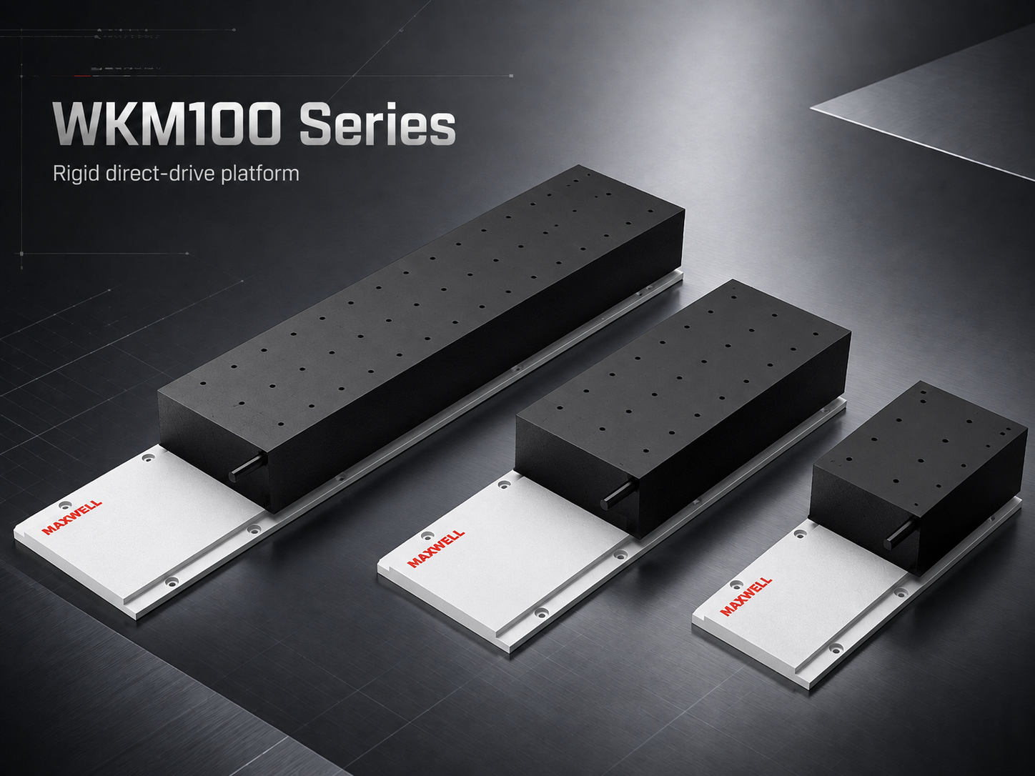
WKM100 configurations extend the force range for larger carriages and higher dynamic demand while keeping model choice tied to the complete motion profile.
WKM150 and WKM200 turn motor sizing into machine sizing
The upper WKM families change the engineering discussion. Higher continuous and peak force places stronger demands on guide support, carriage spacing, base rigidity, bolted joints, cooling layout, cable routing, and emergency stopping behaviour.
At these force levels, selecting the motor after the mechanical frame is already finished can create avoidable problems. The structure may not provide enough stiffness, installation clearance, service access, or a suitable thermal path.
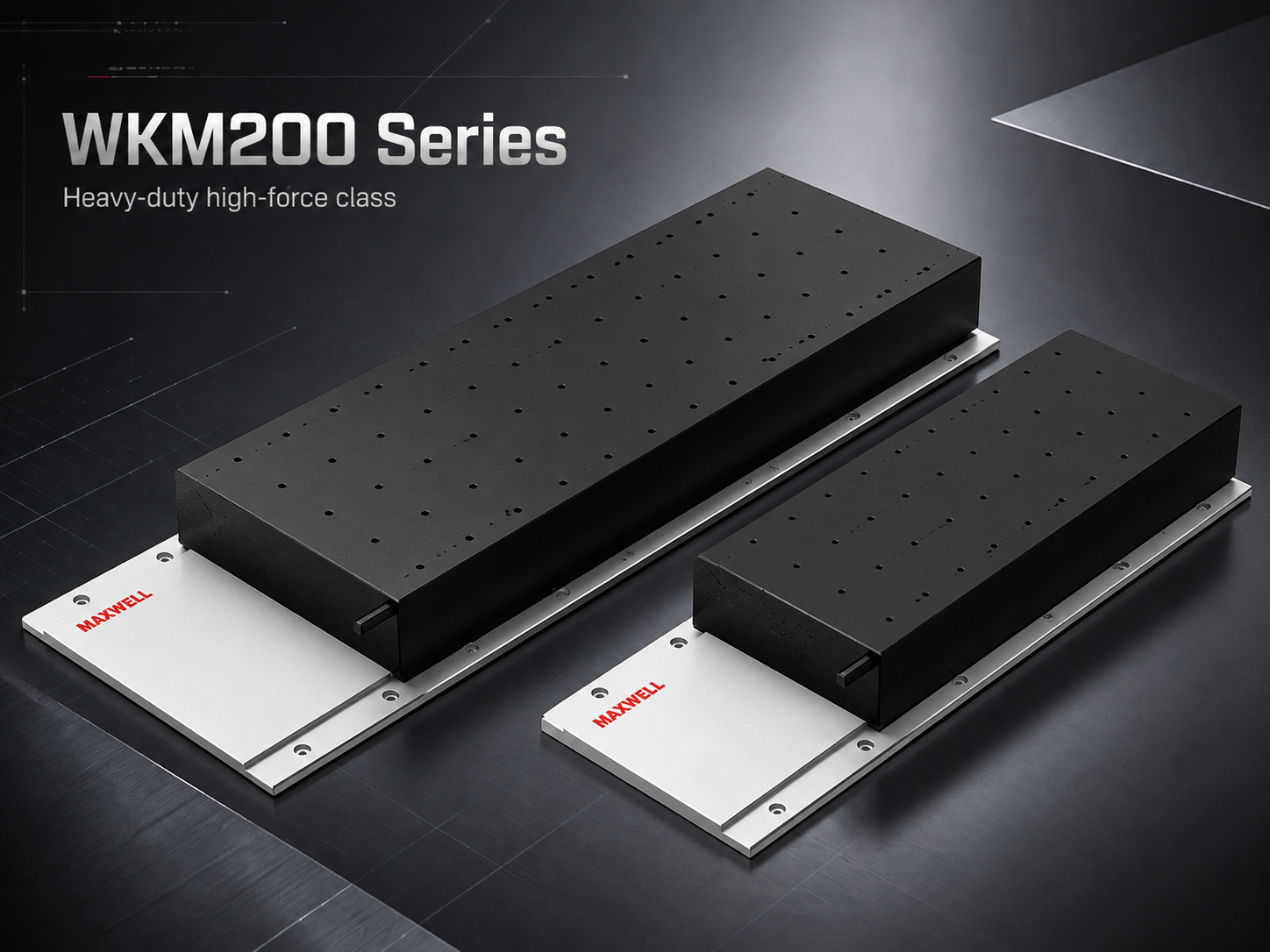
WKM200 represents the upper end of the WKM range, where force capability must be matched with the guide structure, machine base, cooling arrangement, and complete axis architecture.
A powerful motor cannot repair a weak force path. If the base twists or the carriage plate bends under acceleration, additional motor force can make vibration worse. For WKM150 and WKM200 projects, mechanical design and motor selection should progress together.
Payload, Acceleration, Duty Cycle and Cooling
Moving load defines inertia, acceleration converts it into dynamic force, process conditions add external resistance, and the complete production cycle determines how long the motor must sustain that effort. Keeping these inputs separate prevents one broad safety factor from hiding the actual limiting condition.
Build the load figure from the finished moving assembly
Early machine concepts often contain only part weight and fixture weight. As the design develops, process hardware and services can add substantial mass. Final sizing should use a near-complete moving assembly rather than the earliest payload estimate.
Workpiece, tray, carrier, or fixture
Moving tooling plate and adapter structure
Laser, camera, probe, dispensing, welding, or assembly head
Sensors, lighting, brackets, covers, and guards
Cable carrier and its moving cable section
Air, vacuum, coolant, or extraction services
Upper motion axes mounted on the carriage
Variable payload requires more than one operating case. A fixture may move empty during part of the cycle and loaded during another. Product variants can also change tooling mass or center of gravity.
The heaviest state often controls inertial force, but it may not control every performance target. A lighter configuration with a taller center of gravity can create more vibration even though the mass is lower.
Convert cycle time into an actual motion profile
A statement such as “one cycle every two seconds” is not enough for reliable sizing. Two machines can share the same total cycle time while placing very different force and thermal demands on the motor.
Acceleration from the start position
Constant-speed travel where the move allows it
Deceleration before the target
Settling before measurement or processing
Process dwell or controlled process motion
Return acceleration and travel
Idle time before the next cycle
This breakdown shows where peak current occurs and how long it lasts. It also shows whether enough low-load time exists for heat to dissipate before the next demanding movement.
Short moves can contain almost no steady-speed section. The axis accelerates, starts decelerating, settles, and repeats. In these systems, motor force and mechanical settling are closely linked.
Settling time belongs in the cycle-time calculation
Industrial throughput depends on usable process time, not only travel time. An inspection camera cannot capture stable data while the bridge is still vibrating. A laser process gains little from faster positioning if the gantry then needs extra settling time.
The fastest commanded acceleration is not always the fastest production solution. A slightly softer jerk profile can reduce structural excitation enough to shorten the complete cycle.
Mechanical stiffness can produce the same improvement without reducing acceleration. Wider guide spacing, shorter tooling overhang, stronger mounting plates, and direct force paths allow more of the motor's capability to become useful motion.
Horizontal and vertical axes need different force budgets
On a horizontal axis, gravity acts mainly through the guide bearings. Motor demand comes primarily from acceleration, friction, process load, and service drag.
Vertical motion adds a gravity component along the travel direction. The motor must support the moving mass even when acceleration is zero, then produce additional force during upward acceleration.
Downward travel creates a different operating condition because gravity acts with the motion. An inclined axis sits between these two cases, so mounting direction should be defined before final sizing.
Vertical-axis engineering also includes power-loss and emergency behaviour. Normal motor thrust does not replace a machine-level safety strategy. Braking, mechanical retention, controlled stopping, and risk assessment should be handled separately.
Cooling should follow sustained thermal demand
Cooling should solve a calculated thermal problem. A larger motor does not automatically need the most complex cooling method. Production duty, mounting, ambient temperature, and the available heat path should drive the choice.
Natural heat dissipation can remain practical when sustained force is moderate and the installation allows heat to leave the motor effectively. Long process dwell or idle periods can reduce thermal accumulation between demanding moves.
Air-assisted cooling can improve heat removal where the machine environment allows it. Dust, optical contamination, process cleanliness, guarding, and airflow access still need consideration.
Water-assisted thermal management can become relevant when the sustained operating condition requires more heat removal. It also adds hoses, fittings, service connections, routing constraints, and moving mass when coolant lines travel with the carriage.
Those services return directly to the mechanical calculation. A coolant hose changes cable-carrier space, bending behaviour, moving mass, and drag. Cooling is part of axis integration rather than an accessory added after motor sizing.
Thermal decision: establish sustained force, cycle time, local temperature, enclosure conditions, and available heat removal first. Then select the simplest cooling arrangement that provides suitable operating margin.
The production enclosure can behave differently from the test bench
Motor conditions should be reviewed in the expected machine environment rather than only in open factory air. Covers and guarding can restrict convection, while drives, process equipment, lighting, and nearby motors can increase local temperature.
A motor mounted close to a heat-producing process can experience a different thermal environment from the same configuration on an open bench. This difference becomes more important as continuous thrust demand increases.
Ambient information should describe the area around the axis. Enclosure condition, nearby heat sources, ventilation, contamination, and available cooling utilities all help establish a more realistic thermal margin.
Frame Rigidity, Encoder and Thermal Management
Direct drive removes belts, screws, gearboxes, and couplings from the force path. It does not remove compliance from the machine frame. Electromagnetic force acts directly between the motor elements and the supporting structure, so weak mechanics can become more visible as force increases.
This is why higher-force WKM sizing should progress together with guide, carriage, base, feedback, and thermal design. The motor is only useful when the surrounding machine can convert its force into stable process motion.
The frame carries every acceleration reaction
Every force that accelerates the carriage also acts through the supporting structure. Thin plates, long unsupported spans, flexible gantries, and weak joints can deflect even when their static load capacity looks acceptable.
Structural deflection affects more than final position. It can introduce resonance inside the servo-control bandwidth. The controller may then reach a stability limit before the motor reaches its useful dynamic capability.
A rigid force path gives the control system a better foundation. Shorter support spans, suitable section thickness, wider guide spacing, stable joints, and direct load transfer can improve machine response before advanced tuning becomes necessary.
Larger WKM projects deserve particular attention because stronger acceleration forces can expose bending and torsion near the motor, guide blocks, gantry beam, or process tooling.
Guide capacity is not the same as guide stiffness
A linear guide may carry the static load safely while remaining too flexible for the desired dynamic response. Rail spacing, carriage spacing, overhang, preload, lubrication, alignment, and mounting support all affect the result.
A tall process head provides a common example. Acceleration creates a moment above the guide plane. The motor may follow the command accurately while the process point moves because the supporting structure bends.
Iron-core integration also introduces magnetic attraction into the mechanical design. The guide and mounting structure must maintain the intended geometry while carrying both machine load and electromagnetic forces.
Air-gap control belongs in the mechanical layout review. The design should not depend on a thin carriage plate remaining perfectly undeformed under every force condition.
Encoder resolution does not equal machine accuracy
High encoder resolution provides detailed feedback, but it cannot automatically create an accurate axis. Scale accuracy, readhead alignment, mounting stability, controller interpolation, thermal expansion, and structural compliance all influence final process position.
The feedback requirement should start from the process. Repeatability, absolute positioning accuracy, velocity stability, and settling time are different targets and should be stated separately.
Encoder placement also matters. A scale located close to the controlled guide path measures motion more directly. If significant flexible structure sits between the feedback point and tooling, the encoder can report a stable coordinate while the process point continues moving.
This issue becomes more important as force and acceleration rise. Greater dynamic loading can excite structural deflection more strongly, making feedback location and mechanical stiffness part of the same positioning problem.
Cable and hose behaviour can become a servo disturbance
Cable carriers are often treated as secondary service components. In a direct-drive axis, changing cable drag can appear directly in the motion system. Coolant hoses, vacuum tubes, extraction lines, and electrical cables create similar effects.
Stable routing makes these forces more predictable. Suitable bend radii, sensible fixed points, controlled bundle size, and consistent cable-chain geometry help reduce changing disturbance across the stroke.
Long travel deserves extra review because cable-chain behaviour can differ near the middle and ends of the axis. A system tuned only around the center position may not show the worst drag condition.
Every moving service also adds mass. Once cooling, vacuum, process gas, sensing, and power cables are included, the additional load can become significant on a high-acceleration carriage.
Thermal management also protects positioning stability
Motor heat is only one part of machine thermal behaviour. Guides, bearings, servo drives, process equipment, lighting, coolant systems, and nearby structures all change temperature during production.
Thermal growth can alter guide geometry, scale length, tooling position, and machine alignment. In precision equipment, these effects can matter even when the motor itself remains within an acceptable temperature range.
Warm-up behaviour deserves attention where process stability is important. A stage adjusted while cold may not behave exactly the same after several hours of repeated operation.
Heat-source placement can reduce the problem before compensation is required. Keeping strong heat sources away from critical metrology structures and using a mechanically balanced layout can improve long-term stability.
Servo tuning cannot repair a flexible machine
Controller tuning works best when the mechanical structure is already stable. Once a structural mode enters the useful control range, increasing servo gain can increase oscillation instead of improving response.
The commanded motion profile also affects vibration. Very abrupt jerk can excite a flexible tooling bracket or gantry even when the calculated peak force remains acceptable.
A controlled acceleration profile can reduce structural excitation in suitable applications. The best setting balances travel time, peak force, settling, and process stability rather than maximizing one number.
The useful target is the shortest stable production cycle that the complete axis can repeat. That keeps motor sizing tied to real machine output instead of an isolated acceleration specification.
Heavy-Duty Laser, Semiconductor, Inspection and Industrial Positioning Scenarios
Industry name alone should not decide whether WKM is appropriate. The better signal is the motion problem inside the machine: moving mass, dynamic force, repeated duty, process sensitivity, and structural capability.
Laser processing: dynamic transfer and controlled process motion
A laser axis can carry much more than the optical or processing head. Height-control hardware, sensors, extraction components, protective structures, gas lines, service cables, and process tooling can add significant moving mass.
The same axis may also operate in two different modes. Rapid repositioning between process paths creates short high-force acceleration events, while controlled cutting, scanning, or treatment motion can create a longer sustained load.
Large gantries add a structural constraint. Beam bending and torsion can turn stronger acceleration into process-head vibration. WKM provides value when the gantry and guide system are designed to carry the reaction force rather than when a larger motor is used to compensate for a weak structure.
Semiconductor and display equipment: force without losing thermal stability
Some semiconductor and display systems carry larger panels, vacuum hardware, inspection bridges, metrology equipment, or multi-component process assemblies. Their moving mass can rise while settling and thermal stability remain important.
This creates a different decision from general heavy industrial positioning. The motor may need more force, but the machine still has to control heat flow, feedback location, process-point vibration, and structural compliance carefully.
If very low disturbance and cog-free motion outweigh iron-core force density, an ironless architecture deserves comparison before the stage is fixed around WKM. The correct motor structure follows the process requirement, not the industry label.
Inspection systems: settling can matter more than top speed
Inspection stages can carry cameras, lenses, lighting, probes, sensors, supporting brackets, and protective covers. Individual components may be light while the completed bridge becomes a substantial moving assembly.
The production metric is not only travel time between inspection points. The stage has to arrive, settle, capture stable data, and leave again. A motion profile that saves travel time but increases vibration can reduce real inspection throughput.
WKM becomes relevant when a larger inspection structure genuinely requires greater dynamic force. Where low disturbance dominates instead, the ironless branch may provide a better starting point.
Industrial positioning: large fixtures and long production duty
Industrial positioning platforms can carry fixtures, test equipment, handling mechanisms, assembly tooling, or complete process stations. These systems can combine heavy moving structures with frequent motion throughout a production shift.
In such cases, continuous motor duty may be more important than one extreme acceleration event. A machine that moves throughout the shift needs a different thermal margin from an otherwise similar stage used only for occasional positioning.
Large platforms also carry more service equipment. Electrical cables, pneumatic lines, vacuum, coolant, and process connections can create substantial moving mass and varying drag over long travel.
Automotive automation: force must support the production rhythm
Automotive equipment can combine component handling, inspection, assembly, positioning, test operations, and process support. Heavy fixtures increase moving mass, while short repeated cycles increase the importance of sustained force and heat management.
For wider system context, SAHO's automotive automation page shows how linear motion fits within complete production equipment. Motor selection should remain tied to the production axis rather than treated as an isolated component choice.
Service access matters as well. Encoder components, guides, cable carriers, cooling connections, and mounting hardware should remain accessible after guarding and surrounding process hardware are installed.
WKM vs WJM, JKB and NK
WKM should not be treated as the automatic next step whenever another motor seems too small. WJM, JKB, and NK solve different engineering problems. The better comparison starts with force requirement, motor structure, vibration sensitivity, installation space, and integration level.
| Series | Best Starting Point | Main Decision |
|---|---|---|
| WKM | Higher-force iron-core direct drive | Use when dynamic or sustained force requires the wider WKM range and the machine structure can support it. |
| WJM | Compact iron-core motion | Use when a smaller envelope already meets the force, duty, and thermal requirement. |
| JKB | Higher-thrust ironless motion | Use when smooth cog-free behaviour and lower disturbance carry greater process value. |
| NK | Integrated direct-drive stage | Use when an integrated stage reduces unnecessary custom mechanical integration. |
WKM vs WJM: higher force or a smaller package?
WKM and WJM both follow an iron-core direct-drive direction, but their practical positioning differs. SAHO's compact iron core linear motor range is the better starting point when installation space is restricted and the required force remains within the smaller architecture.
A compact motor can reduce moving mass, machine width, drive demand, and structural burden. If WJM already meets peak force, continuous duty, and thermal margin, choosing WKM simply because it is larger adds little engineering value.
WKM becomes more relevant when total moving mass, acceleration, process force, or sustained duty pushes beyond that compact operating region. The boundary should come from the motion profile rather than product hierarchy.
WKM vs JKB: iron-core force density or ironless smoothness?
JKB changes the motor structure rather than simply changing the frame size. SAHO's high thrust ironless linear motor range is relevant where cog-free force production, low disturbance, and smooth motion are important process requirements.
This difference matters in optical scanning, inspection, semiconductor, and other vibration-sensitive stages. WKM takes the stronger position when iron-core force density, larger moving structures, and sustained industrial force dominate the decision.
Within the ironless branch, JKA is better aligned with lower-force, low-vibration precision motion, while JKB extends ironless operation into higher thrust levels. This distinction matters because “precision” and “heavy-duty” are not product families by themselves; required force and disturbance sensitivity still decide the structure.
The comparison should remain practical. Moving mass, acceleration, settling, vibration tolerance, continuous duty, thermal conditions, and available space can change the preferred motor structure even when more than one family appears able to meet the basic force requirement.
WKM vs NK: custom axis or integrated stage?
WKM is a motor family. The guide arrangement, carriage, feedback mounting, cable management, covers, and machine frame remain part of the custom axis design. This freedom is valuable when a heavy machine requires unusual geometry, wide guide spacing, or purpose-built tooling.
The linear motor stage route addresses a different requirement. An integrated module can reduce mechanical development when the available stage architecture already fits the stroke, load direction, and machine layout.
The choice is partly about integration responsibility. WKM provides greater freedom around the motor. NK can simplify implementation when a complete direct-drive stage is the more efficient machine-building route.
Useful family filter: start with the motion requirement and integration level. Stay with WKM when higher iron-core force is genuinely required, step down to WJM when the compact range is sufficient, move toward JKB when low-disturbance ironless motion becomes more important, or use NK when a complete stage is the better mechanical solution.
Project Data Required for WKM Sizing
Once WKM appears to be the right motor family, the project should move from general comparison to actual sizing data. A request containing only payload and stroke still leaves too many unknowns for a reliable model decision.
The most useful submission describes the moving assembly, stroke, speed, acceleration, complete cycle, required motion quality, installation direction, thermal environment, and existing control architecture. This allows dynamic force, sustained force, and mechanical integration to be reviewed together.
| Project Item | Information to Prepare |
|---|---|
| Moving load | Payload, fixture, carriage, tooling, cable carrier, hoses, covers, upper-axis mass, and center-of-gravity information where relevant |
| Stroke and envelope | Required working stroke plus available machine length, width, and installation clearance |
| Motion profile | Target transfer speed, process speed, acceleration, deceleration, move time, and jerk limits where relevant |
| Production duty | Cycle time, process dwell, moves per minute, duty cycle, idle periods, and expected operating hours |
| Process requirement | External process force, required accuracy or repeatability, settling time, and velocity stability where applicable |
| Installation direction | Horizontal, vertical, inclined, inverted, gantry, or stacked-axis arrangement |
| Thermal environment | Ambient condition, enclosure, nearby heat sources, contamination, airflow, and available cooling method |
| Feedback and control | Encoder, servo drive, controller, feedback interface, electrical architecture, and synchronization requirements when already defined |
A machine drawing can be more useful than another catalog number
For larger WKM projects, a simple cross-section or assembly drawing can reveal information that is difficult to describe in text. Guide spacing, tooling overhang, motor position, cable route, cooling space, and the center of gravity become visible immediately.
This is particularly useful when the project involves a wide gantry, stacked axes, tall tooling, or unusual mounting orientation. Mechanical geometry can change the practical motor choice even when the calculated force remains the same.
Working stroke and installation envelope should be stated separately
Useful process stroke is not the same as total axis length. Home position, sensor location, deceleration allowance, end clearance, mechanical protection, and service access can all consume additional space.
Long travel also affects cable routing, stator layout, structural straightness, and encoder installation. Providing both usable travel and total available envelope helps prevent a motor selection that fits the force requirement but not the machine.
Transfer speed and process speed may be different
Many industrial machines use a high transfer speed between work areas and a lower controlled speed during the actual process. Supplying only the highest number can hide the part of the cycle that produces the greater sustained force or thermal load.
Acceleration and deceleration should be supplied directly when known. If only move distance and required move time are available, the intended profile should accompany those values so the dynamic demand can be reconstructed more reliably.
Accuracy, repeatability and settling should not be merged into one number
Repeatability describes how consistently the stage returns to the same position. Absolute accuracy describes how closely the real location follows the commanded position across travel.
Settling adds another requirement. A stage may enter a position tolerance quickly but continue vibrating too much for measurement or processing. This is why settling time should be specified separately in inspection, laser, metrology, and other high-response applications.
Existing encoder and controller choices should be included early
When the servo drive, controller, encoder interface, or electrical architecture has already been selected, that information should enter the sizing discussion before the final motor is fixed.
Gantry systems can add synchronization requirements, while multi-axis equipment may introduce additional control constraints. Early control information helps avoid mechanical sizing around a combination that becomes difficult to integrate later.
For projects still deciding between belts, screws, direct-drive motors, or integrated modules, SAHO's linear motion solutions for industrial automation page provides the broader architecture-level comparison. Once WKM has been identified as the likely motor family, the sizing inputs above become the more relevant next step.
FAQ
Is WKM a complete linear motor stage?
No. WKM provides the iron-core mover and stator components that generate direct-drive force. A complete stage also needs guideways, a carriage and support structure, encoder feedback, a servo drive, a controller, cable management, and any required cooling system.
This distinction matters during purchasing because the WKM force range does not describe the payload or rigidity of a finished guided axis. Those limits must be established from the complete mechanical and control design.
When should WKM be selected instead of WJM?
WKM is the stronger direction when peak or sustained force moves beyond the practical compact range of WJM. Higher moving mass, stronger acceleration, greater external load, or heavier duty can all move the project toward WKM.
WJM remains preferable when the smaller iron-core envelope already meets force, duty, and thermal requirements. Using the larger family without a defined need can add mass and integration complexity.
How do payload and acceleration affect WKM sizing?
Payload contributes to the moving mass, while acceleration converts that mass into inertial force. Tooling, fixtures, moving cables, hoses, covers, brackets, and upper axes should also be included because they accelerate with the carriage.
External process force, friction, gravity, and service drag add further demand. Peak force and continuous thermal duty should then be checked separately.
Does higher WKM force always require water cooling?
No. Cooling depends on sustained force, cycle time, mounting, enclosure conditions, local temperature, and the available heat path. Intermittent operation and continuous operation can create very different thermal demands.
Water-assisted cooling can become useful for demanding sustained operation, but it adds hoses, fittings, moving mass, service requirements, and routing constraints. It should solve a defined thermal requirement rather than follow motor size automatically.
When is JKB or an NK module a better alternative?
JKB deserves comparison when cog-free, smooth, low-disturbance motion is more important than the iron-core force-density direction. Sensitive optical, inspection, scanning, and semiconductor stages can fall into this category.
NK becomes relevant when an integrated stage reduces unnecessary custom mechanical development. The better route depends on force, vibration sensitivity, available space, stroke, machine structure, and preferred integration level.
From Motion Requirements to a WKM Sizing Decision
WKM is most appropriate when the axis genuinely needs greater iron-core direct-drive force and the surrounding mechanical structure can support it. Peak thrust should match the hardest short event, while continuous thrust should reflect the repeated cycle and real thermal environment.
Guide stiffness, tooling geometry, settling, encoder location, installation direction, cable behaviour, and heat removal then determine whether additional motor force improves production performance or simply places more demand on the machine.
Before final model confirmation, three actions provide the clearest next step:
Complete the motion profile. Record total moving load, payload variation, stroke, transfer speed, process speed, acceleration, external force, cycle time, and duty cycle.
Review mechanics and thermal conditions together. Confirm installation direction, guide arrangement, frame rigidity, accuracy or repeatability requirement, settling target, environment, and cooling conditions.
Prepare the feedback and control data. Include encoder, servo drive, controller, electrical architecture, and synchronization information when those items are already defined.
These inputs prevent a high force linear motor from being selected only by a maximum thrust figure. They allow WKM to be matched to the actual load, acceleration, duty cycle, thermal conditions, mechanical structure, and control architecture of the machine.
Submit the core motion data through the contact form. If a machine drawing, force-time profile, or control specification is available, mention it in the request so the engineering team can confirm how to provide the file for review.