

Date:2026-09-06 Click:147
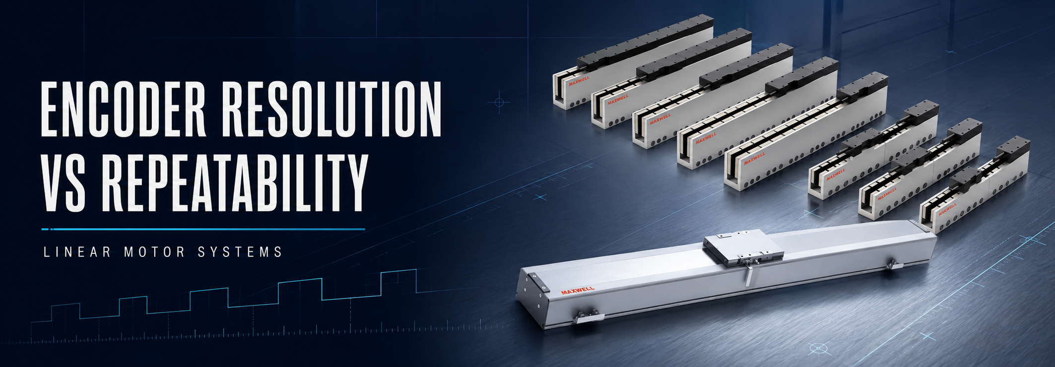
A finer linear motor encoder resolution does not automatically create better repeat positioning.
It only gives the controller smaller feedback increments. Scale accuracy, interpolation quality, mounting, cable noise, machine stiffness, thermal drift, and servo tuning shape the final result. A sensible selection process therefore starts with the required machine outcome, not the smallest number printed on an encoder specification.
For an inspection axis that must settle before a camera exposure, the useful question is whether the measurement stays stable through that exposure. SAHO’s low-vibration ironless linear motor range is relevant to that discussion, but the motor, guideway, frame, encoder and controller all contribute to the result.
Product scope: JKA and JKB supply ironless mover-and-stator components. A complete axis also needs guideways, a carriage and machine structure, encoder feedback, a servo drive, a controller and cable management. MNK uses a protected module architecture; confirm the feedback supplied with the selected configuration. Encoder resolution alone is not an installed-axis accuracy specification. |
JKA for Smooth, Low-Vibration Precision Motion

A camera or probe that pauses at each measurement point needs the axis to arrive smoothly and stay settled. In a JKA-based system, feedback quality supports that low-speed control and repeatable stop. A finer output increment becomes useful when the guide, fixture and reader alignment can support it.
For precision inspection or assembly, the functional point may sit above the carriage. Encoder placement and Abbe offset deserve early review. The feedback interface must also match the selected servo controller, cable routing, and homing strategy.
What the Encoder Number Actually Tells You
Several specifications often appear beside each other, yet they describe different behaviors. Resolution describes the smallest feedback increment available to the controller. Accuracy describes how closely reported position follows true position across a stated range. Repeatability describes how closely the axis returns to the same position under defined conditions.
An axis can repeat closely around a position with a systematic offset, or display fine increments while returning to a much wider position band. Read these specifications separately before comparing two feedback systems.
| Term | What it describes | What it does not prove |
|---|---|---|
| Resolution | Smallest reported or interpolated position increment | Position accuracy, repeat return behavior, or process quality |
| Scale accuracy | Difference between indicated and reference position over a defined length | Installed axis performance after mounting and thermal effects |
| Repeatability | Spread of repeated approaches to the same commanded position | Accuracy at every position or under different test conditions |
| Positioning accuracy | Difference between commanded and measured position under stated conditions | Dynamic path quality or settling behavior by itself |
A controller may accept very small command increments. Those commands do not guarantee equivalent physical motion. Friction, structural compliance, quantization, current-loop behavior, and feedback noise can mask small changes. The controller may display more decimal places than the machine can physically resolve.
A small command step has value when it produces a measurable improvement at the process point. Extra display digits alone do not show whether the feedback, mechanics and servo response can support that movement.
Repeatability has little meaning without a test definition. Approach direction, travel distance, payload, speed, acceleration, dwell time, temperature, and sample count all influence the result. For example, a one-direction approach can hide reversal effects that appear during bidirectional positioning.
A short cold test may not represent a production cycle. Motor heating, bearing temperature, frame expansion, and cable-carrier forces can change after repeated motion. The acceptance method should reflect the actual duty cycle and process direction.
An error budget separates the main contributors before hardware selection. It may include scale error, interpolation error, mounting error, thermal change, structural deflection, servo following error, and external measurement uncertainty. However, these terms should not be added blindly because some are systematic while others are random.
A practical budget assigns an allowable share to each contributor. Then, validation checks whether the installed axis stays within the combined limit. This method also reveals where extra spending matters. A finer encoder brings little benefit when the machine frame dominates the position spread.
How to Select Linear Motor Encoder Resolution
Start with what the process must deliver. A placement head may need repeatable endpoints, a scanning sensor may need stable velocity, and a dispensing axis may need accurate coordinated motion. State the required endpoint repeatability, absolute position, path accuracy or settling time at the functional point, including the coordinate direction and any angular sensitivity.
Next, separate necessary performance from preferred performance. An unnecessarily tight target can raise cost and commissioning difficulty. A vague target transfers risk into acceptance testing, where correction becomes slower and more expensive.
That target needs a real motion profile behind it: moving mass, payload range, centre of gravity, stroke, speed, acceleration, jerk and cycle timing. Installation direction and external process forces belong in the same review because they change motor demand, structural deflection and cable loading.
The worst case may not be the heaviest payload. A lighter fixture can have a larger offset or lower stiffness. Every distinct configuration should be checked against both dynamic and positioning requirements.
Trace how position reaches the controller, from the scale and readhead through the interface, coordinate conversion and compensation functions. Knowing where interpolation occurs makes it easier to compare feedback options and locate a problem during commissioning.
The measurement line should be compared with the process line. If they differ, note every structural element between them. In particular, record offsets that convert angular motion into linear process error.
The process tolerance must cover more than feedback. Geometry, thermal behaviour, servo control, fixture deflection and measurement uncertainty each need an allowance, with reserve for assembly variation and ageing. A design that consumes the full tolerance on paper leaves little room for commissioning.
Systematic errors may support calibration when they remain stable. Random or condition-dependent errors need another strategy. The budget should label each contribution as correctable, repeatable, drifting, or uncertain.
An encoder that works well on an open bench may be awkward inside a warm, crowded machine. Temperature, contamination, vibration, cable flexing and electromagnetic disturbance affect reliability; access for alignment and cleaning affects serviceability. Evaluate those conditions at the planned scale and readhead location.
The environmental review should match the actual enclosure and machine layout. General room conditions do not describe local heat or cable routing. Measurements near the scale and reader location offer more useful evidence.
The control system also determines which feedback options are practical. Signal type, input capability, count rate, reference handling, alarms, diagnostics and compensation-table support should be checked together before a model is ordered.
Diagnostic visibility deserves special attention. Raw signal monitoring, feedback alarms, following-error logs, and trend data can shorten troubleshooting. Without useful diagnostics, a small intermittent feedback problem may resemble a mechanical or tuning fault.
Agree on verification while the layout can still accommodate it. Specify the external reference, target positions, approach directions, payload, temperature and sample count. Peak-to-peak range, standard deviation and maximum absolute position error describe different results; a ± value cannot be compared directly with a full range unless both definitions are known.
Planning the test before ordering also protects access for measurement. A process point hidden by guarding may need a temporary metrology target designed into the fixture. Retain raw samples so the result can be recalculated if the acceptance statistic changes.
Compare Resolution Against the Acceptance Band
Suppose a stop-and-capture inspection axis must remain within ±1 μm of its target during exposure. The total position band is 2 μm. A feedback increment of 1 μm/count divides that width into only two count intervals; 0.1 μm/count provides twenty. The finer option gives the controller more position information, but neither figure proves that the camera or probe will stay within the required band.
This is an illustrative comparison, not a SAHO performance specification or a universal selection ratio. Scale accuracy, interpolation error, standstill jitter, mounting and thermal effects must still fit the requirement. A tenfold improvement in output resolution does not establish a tenfold improvement in positioning.
When finer feedback is worth reviewing: the present increment is too coarse for the control band, and independent measurements show that mechanics and signal quality can support an improvement. If the dominant error follows temperature, cable drag or fixture deflection, correct that source before paying for additional resolution.
Compare candidate encoders at the same stroke, speed, interface and operating conditions. Request scale accuracy, interpolation or sub-divisional error, standstill jitter, allowable readhead alignment, output format and maximum operating speed. Keep these as separate specifications rather than reducing them to one resolution number.
Match the Encoder Interface to the Controller
Controller compatibility includes more than connector shape. Interface protocol, signal format, maximum input rate, reference behavior, error monitoring, cable limits, and interpolation location all matter. The encoder and controller documentation should be reviewed as one interface package.
For incremental A/B feedback, check maximum counting rate at the intended speed. Required decoded counts per second equal travel speed divided by distance per decoded count, using consistent units. Confirm whether the controller specification refers to signal cycles or decoded edges; these are not interchangeable. For an absolute serial interface, check protocol compatibility, update period, transmission delay and diagnostic support instead of applying the A/B count-rate calculation.
For another reference on interface, installation and environmental checks, see Renishaw’s encoder selection considerations for precision stages.
Why Fine Feedback Can Still Produce Uneven Motion
Many linear feedback systems create fine position counts by interpolating periodic scale signals. Interpolation divides one signal period into smaller electronic increments. The advertised output step may be much finer than the physical pitch. The quality of those subdivisions depends on signal shape, amplitude balance, phase relationship, and electronic processing.
Interpolation error appears when the calculated subdivisions do not remain evenly spaced. Signal distortion, contamination, alignment error, or gain mismatch can contribute. As the axis moves, this error may create a repeating position pattern tied to the scale period. A finer count alone cannot remove that pattern.
Signal Amplitude, Phase and Electrical Noise
Analog sine and cosine signals need stable amplitude and phase. When one channel differs from the other, calculated position can shift within each cycle. Weak signals reduce noise margin. The result may appear as position ripple, velocity ripple, or inconsistent settling near a target.
Digital feedback simplifies some interface concerns, yet cable integrity still matters. Poor shielding, unsuitable grounding, connector problems, or excessive cable length can corrupt communication. Interface type and controller compatibility must be confirmed before the axis layout becomes fixed.
The servo loop reacts to measured position, not to an ideal position. Electrical noise can look like small physical movement. The controller may then command corrective current even while the carriage remains nearly still. This behavior can increase audible activity, heat, current variation, and settling time.
Noise sources often include motor power cables, drive switching, grounding loops, nearby actuators, and poorly separated signal wiring. However, excessive filtering is not a free solution. Strong filtering adds delay, reduces usable bandwidth, and can hide real motion that the controller needs to see.
Keep encoder cables separated from motor power and high-current switching cables, and follow the encoder and drive documentation for shielding and grounding. Minimise connector transitions in moving cable paths; check the bend radius and flex rating of every moving feedback cable. Inspect raw signal quality before applying heavy software filtering.
Reader-head alignment affects the working gap, signal level, and tolerance to motion. Pitch, yaw, roll, and height variation can change that gap along the stroke. A scale may perform well on a small bench yet show weak regions after installation on a long structure.
Scale mounting also affects thermal behavior. A rigidly bonded scale can follow the mounting surface differently from a scale with another retention method. Thermal expansion paths should match the accuracy strategy. The scale, support surface, and reference metrology must share a clear datum plan.
In an incremental system, a reference mark establishes the coordinate relationship after startup. It does not correct every position error along the travel. Homing repeatability depends on approach conditions, detection method, servo state and the reference feature. Use the manufacturer-approved homing sequence with consistent approach conditions.
After homing, the controller relies on the feedback system and stored coordinate model. If absolute position is required after power cycling, the selected feedback architecture must support that requirement. Otherwise, a reference routine remains part of machine startup and recovery planning.
Diagnostic clue: a periodic position or velocity ripple often points toward interpolation, alignment, or signal quality. A drift that grows with time or stroke more often suggests thermal or geometric influence.
When the Encoder Reading and Tool Position Disagree
Direct drive removes mechanical transmission elements, but it does not remove mechanics from the axis. The carriage still rides on bearings or guideways. The payload still applies forces and moments. The base, brackets, covers, cables, hoses, and machine frame still deform under load.
Mechanical effects can change the relationship between the encoder reading and the process point. The reader head may report a stable carriage position while a distant tool tip moves because of structural deflection. Feedback placement and point-of-interest geometry deserve equal attention.
Guideway Geometry, Load Distribution and Abbe Offset
Guide preload, lubrication, straightness, and mounting flatness influence motion resistance. Small changes in resistance can alter settling behavior, especially near low speed. Uneven loading can create pitch or yaw that shifts the process point even when carriage feedback appears stable.
Payload position matters as much as payload mass. An overhung load increases moments around the guide system. Two fixtures with equal mass can produce different tracking and repeatability. The selection package should include center-of-gravity location, not only a single load value.
An Abbe offset exists when the measurement line does not coincide with the process point. Angular error then becomes linear position error at the offset distance. In practical terms, a small carriage rotation can cause a larger tool-tip shift when the tool sits far above the scale.
Reducing the offset improves measurement relevance. Where geometry prevents that change, the structure must control angular motion more tightly. Alternatively, external metrology at the actual process point can reveal the difference between encoder position and functional position.
Moving cables and hoses apply force to the carriage. That force may vary with position as a cable carrier bends and unbends. A poorly supported bundle can create asymmetric load, disturb low-speed motion, or change the final approach near one end of travel.
Cable routing should therefore form part of the motion design. Bend radius, fill, separator use, moving length, fixed-end location, and strain relief all matter. During validation, repeatability should be checked at several stroke positions because cable influence rarely stays constant.
A precise motion component cannot correct an unstable foundation. If the base twists during bolt tightening, the guide geometry changes. A frame can deform under acceleration or nearby machine loads. The resulting error may depend on motion direction, payload, and machine state.
Mounting preparation should define datum surfaces, flatness checks, bolt sequence, and support conditions. Afterwards, geometric verification must occur on the assembled machine. Component inspection and machine inspection answer different questions, so neither one replaces the other.
Thermal Drift Can Dominate Fine Feedback
Temperature changes alter the scale, base, guideway, fixture, and workpiece. Motor losses and bearing motion create local heating. Even when each change is small, different expansion paths can shift the process point relative to the feedback datum.
Thermal behavior should be evaluated over the full production cycle. A cold start, warm steady state, short stop, and long idle may produce different offsets. Acceptance criteria should state the required warm-up condition and allowable ambient range.
| Observed pattern | Likely areas to inspect | Useful next check |
|---|---|---|
| Error changes with approach direction | Guide friction, cable force, structural hysteresis, servo behavior | Compare unidirectional and bidirectional cycles |
| Error grows after repeated cycling | Thermal drift, preload change, current-related heating | Log temperature and position from cold start to steady state |
| Error varies by stroke position | Scale map, geometry, reader gap, cable carrier, base deformation | Measure several positions across the usable stroke |
| Tool result changes while carriage reading stays stable | Abbe offset, fixture compliance, process force, external vibration | Measure at the functional point, not only at the carriage |
What Settling Time Reveals About the Axis
The encoder provides information, while the servo decides how to act on it. Position, velocity, and current loops must work together. If tuning is too soft, the axis may settle slowly or remain sensitive to disturbance. If tuning is too aggressive, noise and structural resonance may become visible.
A higher-resolution signal can make small deviations observable and improve control where feedback granularity is the limiting factor. Noise and structural vibration still need separate diagnosis: increasing the available counts does not distinguish measurement noise from real movement.
Servo bandwidth cannot be chosen independently from structural dynamics. The carriage, fixture, frame, and process assembly have resonant modes. Raising loop bandwidth toward a structural resonance can reduce stability margin and increase oscillation risk. Higher gain does not always mean better settling.
A useful tuning process identifies resonances before applying aggressive gains. Then, notch filters or mechanical improvements can address specific modes. Broad filtering should remain limited because it can reduce responsiveness across frequencies that do not need correction.
Following Error, Final Position and Settling Criteria
Following error describes the difference between commanded and measured motion during a trajectory. By contrast, final position evaluates the state after motion and settling. An axis can track poorly during acceleration yet reach the final point. Another axis can track well but oscillate near the endpoint.
Both measures matter when process timing depends on motion completion. A test should log peak following error, residual error, and time inside the acceptance band. Otherwise, a repeatable final point may hide a cycle-time problem that limits machine throughput.
Settling time depends on the chosen position band. A wide band produces a shorter reported time, while a narrow band exposes residual vibration. Any comparison must use the same band, sample rate, filter settings, and dwell rule.
The controller should also remain inside the band for a defined period. A single sample inside the limit does not prove stable settling. For precision assembly, inspection, or scanning, the process may require velocity and vibration conditions in addition to position.
Filtering and Feedforward Trade-Offs
Feedback filters can reduce high-frequency noise, but their phase and timing effects must be included in the loop design. Excessive filtering can weaken disturbance rejection or make a displayed trace look smoother than the actual process-point motion.
Filter settings should follow measured evidence. Start with correct grounding, shielding, cable separation, and encoder alignment. Next, identify remaining spectral content. Only then should targeted filtering address frequencies that cannot be solved mechanically or electrically.
Velocity and acceleration feedforward can reduce trajectory error. However, feedforward does not improve the physical encoder signal. It also cannot correct an incorrect mechanical model under every payload. Feedforward tuning should follow stable feedback and basic loop tuning.
Payload changes deserve separate verification. A tuning set that performs well with one fixture may overshoot with another. Where several payload states exist, the control strategy may need gain scheduling or a conservative shared tuning window.
Where JKB and MNK Fit the Feedback Decision
Encoder selection should follow the architecture and operating goal of the complete axis. The required stroke, payload, acceleration, thermal condition, environment, and controller interface all matter. A feedback choice should never be copied from another machine based only on a similar motor name.
The JKA arrangement introduced above uses component-level integration. JKB follows the same approach across a wider thrust range, while MNK provides a protected module architecture. Confirm the encoder model, interface and supplied configuration for the proposed assembly before comparing resolution figures.
JKB for Higher-Thrust Ironless System Requirements
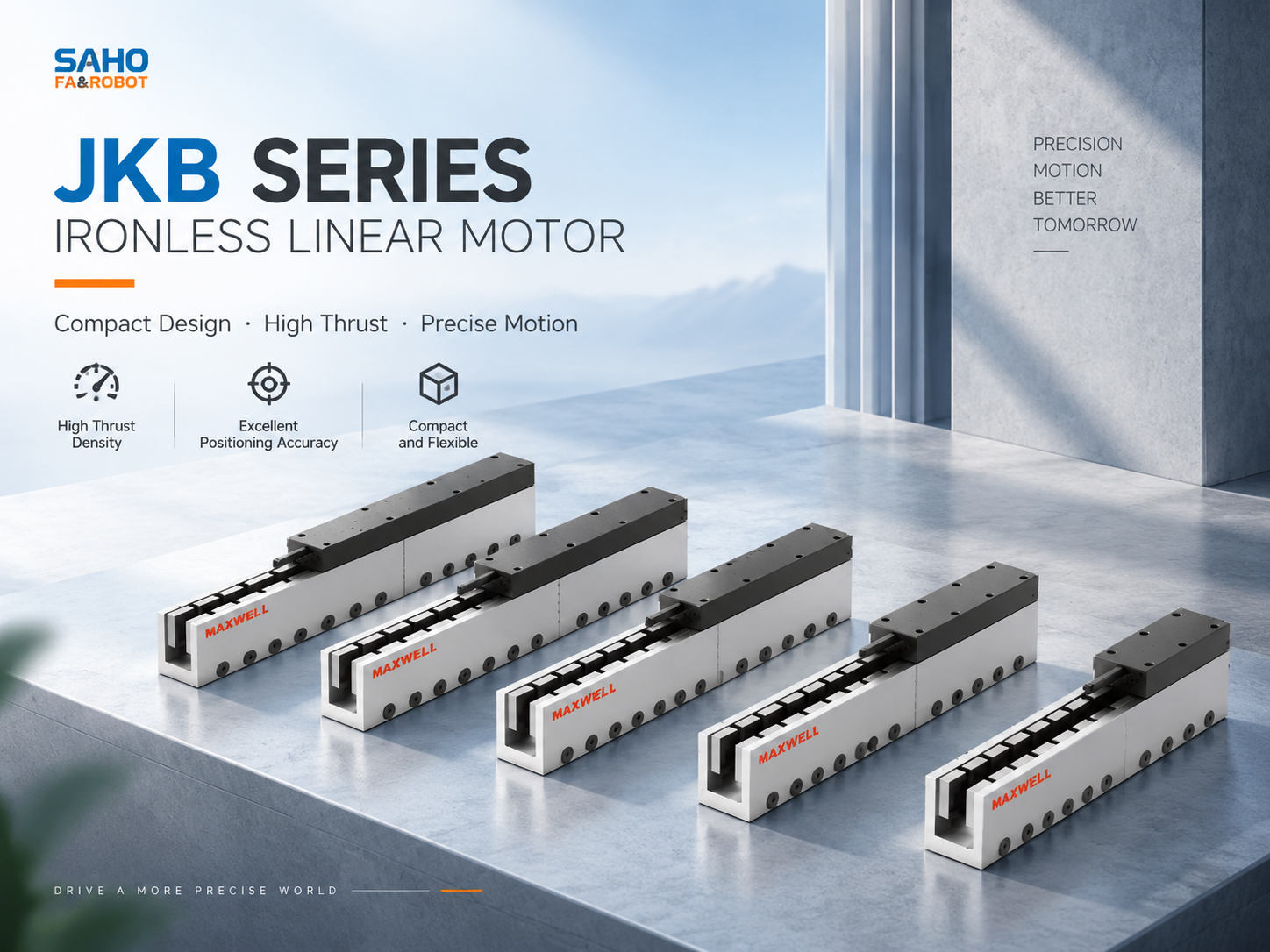
When a larger inspection platform needs more force while retaining ironless motion, the high thrust ironless linear motor range provides a wider thrust choice. Higher acceleration and payload moments put more demand on the base, fixture, thermal path and moving cables. The encoder must be assessed during that motion, not just while the axis is stationary.
MNK for Integrated, Sealed Module Architecture

For a machine builder integrating a protected axis, the sealed linear motor module changes the packaging work. With MNK, confirm the supplied feedback configuration alongside covers, internal geometry, cable exits and mounting. Access to the readhead and connectors matters when the installed system needs inspection or service.
A protected architecture does not remove the need for clean installation. External cable routing, grounding, mounting flatness, and thermal conditions still affect machine performance. Any external process fixture can introduce compliance above the module carriage.
Use these as application priorities, not exclusive capabilities. Both JKA and JKB require checks for low-speed stability, dynamic tracking, settling and thermal behaviour. Choose their motor configuration from force and space requirements; compare encoder options within that axis design. With MNK, also confirm module mounting, cable exits, protection requirements and service access.
Consider the Process, Not Only the Axis
Inspection, dispensing, placement, bonding, and scanning impose different motion demands. For instance, a placement axis may prioritize endpoint settling. A scanning axis may prioritize constant-velocity ripple. A dispensing process may depend on path accuracy and coordinated motion.
In electronic component assembly automation, feedback selection should connect to placement tolerance, cycle time, fixture behavior, and machine metrology. A single encoder specification cannot represent the full production outcome.
Prove the Result Under Production Conditions
Validation should prove installed behavior, not only component capability. The test setup must represent the expected payload, motion profile, temperature, cable arrangement, and controller settings. The external reference must have sufficient performance and valid calibration for the intended conclusion.
Pre-Test Installation Checks:
Confirm mounting surfaces, bolt condition, alignment, and carriage freedom.
Inspect scale cleanliness, reader gap, alignment, and full-stroke signal condition.
Verify encoder cable separation, shielding, grounding, strain relief, and bend radius.
Record controller, drive, encoder, filter, gain, and compensation settings.
Check home and limit sensor logic before full-stroke automatic motion.
Confirm lubrication and payload installation before collecting baseline results.
Before precision measurement, run a slow full-stroke observation. Listen for cable drag and watch feedback status. Inspect whether following error changes at specific positions. Position-dependent behavior can reveal alignment, scale, or cable problems early.
Separate a stable hold from a repeatable return
Command the axis to several positions and hold. Then log reported position, current, and external metrology. This test reveals drift, noise-driven correction, and local structural behavior without the complexity of repeated trajectories.
Hold duration should match the process need. A short hold can show immediate settling, while a longer hold exposes thermal or control drift. Compare behavior near the stroke center and ends because cable force and structure may differ.
Approach each target from the same direction and from a consistent starting distance. Then collect enough cycles to reveal spread. This method isolates repeat return behavior while limiting direction-reversal influence.
The test should include several positions across the usable stroke. Otherwise, local scale, geometry, or cable effects may remain hidden. Record both encoder position and external reference position whenever possible.
Next, approach the same targets from both directions. Differences can reveal structural hysteresis, friction, cable force, or tuning behavior. Although direct drive removes screw backlash, the complete machine can still show direction-dependent effects.
Report direction-specific results rather than merging everything into one number. This distinction supports process decisions. For example, a machine may use a controlled one-direction final approach when the cycle allows it.
Test the move that production actually uses
Run the intended speed, acceleration, jerk, and payload. Then log command position, feedback position, following error, velocity, and settle status. A low-speed bench move does not prove production-cycle performance.
The acceptance report should define the settling band and required dwell time. Note filter and gain settings. A result without control settings cannot support later comparison after maintenance or software changes.
Run the expected cycle until temperature and position behavior reach a representative condition. Measure relevant machine locations, not only room air. Then repeat selected position tests during warm operation.
If the process restarts after idle periods, include restart behavior. Include cooling pauses when they occur in normal production. Thermal validation must follow the real operating pattern rather than a convenient laboratory sequence.
Check the result at the tool or workpiece
Encoder data should be correlated with the functional result. For an assembly process, that may mean placement location. For inspection, it may mean measured feature position. For scanning, it may mean spatial consistency during constant velocity.
This step closes the gap between axis specifications and machine value. If the process result varies while encoder return remains stable, the investigation should move toward fixture, tooling, workpiece, or external disturbance. More encoder counts will not solve that mismatch.
Keep one traceable acceptance record: retain the configuration and test sequence, raw position samples, calculated statistics, calibration record, measurement-setup images, parameter backup, software version and process samples. Record instrument uncertainty, datum, compensation settings and every change made between test runs.
Let the Error Pattern Guide the Next Check
Troubleshooting should change one factor at a time. Otherwise, several simultaneous adjustments can hide the original cause. Start by preserving the failing data, machine state, controller parameters, payload, and temperature condition.
Next, classify the error pattern. Determine whether it follows time, stroke position, direction, speed, acceleration, payload, or temperature. This classification narrows the search more effectively than random gain changes.
If the Error Is Random Near the Target. Inspect feedback noise, grounding, cable routing, and current activity. Also compare the external reference with the encoder reading. If both signals move together, real mechanical motion may exist. If only feedback moves, signal quality becomes more likely.
Then reduce nearby electrical disturbance where possible. A temporary controlled test can separate cable or grounding influence. However, permanent wiring must follow the equipment documentation and machine safety requirements.
If the Error Repeats at Regular Spatial Intervals. A spatially periodic pattern can suggest interpolation or geometry linked to a repeating feature. Compare the period with known scale or mechanical dimensions. Inspect reader alignment and signal quality along the affected region.
Do not assume the encoder is defective. Mounting variation, contamination, or structural motion can disturb a healthy device. The diagnostic goal is to identify the condition that creates the pattern.
If the Error Changes with Direction. Compare one-direction and two-direction approaches under identical conditions. Then inspect cable force, guide behavior, fixture hysteresis, and tuning around reversal. Direct drive removes transmission backlash, yet other elastic and friction effects remain.
A controlled final approach may improve process consistency when cycle time permits. Still, that strategy should not hide an unstable mechanical condition. Acceptance documents should state the approved approach method clearly.
If the Error Grows During Production. Log temperature, current, cycle count, and position over time. Compare cold and warm scale maps. A steady drift points toward thermal expansion or gradual load change, while an abrupt shift may indicate a mechanical or electrical event.
Warm-up procedures can improve consistency when thermal behavior remains predictable. The process must define when production becomes valid. Compensation should use measured, stable relationships rather than assumptions.
If Encoder Position Looks Good but the Process Does Not. Move the measurement point toward the tool, fixture, or workpiece. Then examine structural compliance and external process forces. This comparison often exposes an Abbe offset or flexible mounting path that carriage feedback cannot observe.
Process correlation may also reveal workpiece variation, vision calibration error, or tool condition. Motion data should remain connected to the full machine measurement chain. Axis tuning alone cannot correct every production deviation.
Frequently Asked Questions
Can an encoder upgrade improve an existing axis without changing the motor?
It may help if feedback granularity or signal performance is the demonstrated limitation and the controller supports the replacement. Check the mounting envelope, scale and readhead compatibility, interface, speed limit and referencing method before ordering. Recommission the feedback and verify the axis afterward; an upgrade will not remove fixture deflection or thermal drift.
Does an absolute encoder remove the need for homing?
An absolute encoder can supply position after startup without the reference-mark search used by an incremental system. The machine may still require datum verification, coordinate-offset setup or another manufacturer-defined startup procedure. Confirm position validity, travel limits and recovery behaviour in the complete control system.
What evidence should accompany a proposed encoder configuration?
Request the exact encoder and interface specification, applicable speed and cable limits, installation tolerances, and a test report with stated load, direction, temperature, settling band and measurement method. For JKA or JKB, confirm the integration responsibilities; for MNK, confirm what feedback is included with the quoted module.
Bring the Motion Requirement and Feedback Together
A useful review starts with the required machine result and the feedback configuration being considered. For related system context, review linear motion solutions for industrial automation, then prepare the information below for the relevant JKA, JKB or MNK configuration.
Position and timing: required accuracy and repeatability, approach direction, settling band, dwell time and the process point where the result matters.
Feedback and control: existing or proposed encoder model, resolution, interface, scale length, servo drive, controller, cable length and homing requirements.
Motion and operating conditions: total moving mass, payload range, stroke, speed, acceleration, cycle time, duty cycle, installation direction, cooling and environment.
Layout and evidence: a drawing showing centre of gravity, process-point offset, mounting datum, available space and cable direction. For an existing problem, include cold and warm measurements, error traces and the current test method.
Next step: submit the motion profile and feedback specification with the target position band. The review should establish whether finer resolution would provide useful control margin, which interfaces fit the controller, and how the proposed assembly will be validated under the intended load and operating cycle. |







-
-
 English
 -
 Français
 -
 Deutschland
 -
 Italia
 -
 Polska
 -
 España
 -
 Русский язык
 -
 日語
日語 -
 한국
한국 -
 Türkiye
 -
 português
 -
 بالعربيةês
 -
 Tiếng Việt
 -
 คนไทย
คนไทย -
 简体中文
简体中文 -
繁體中文
-