

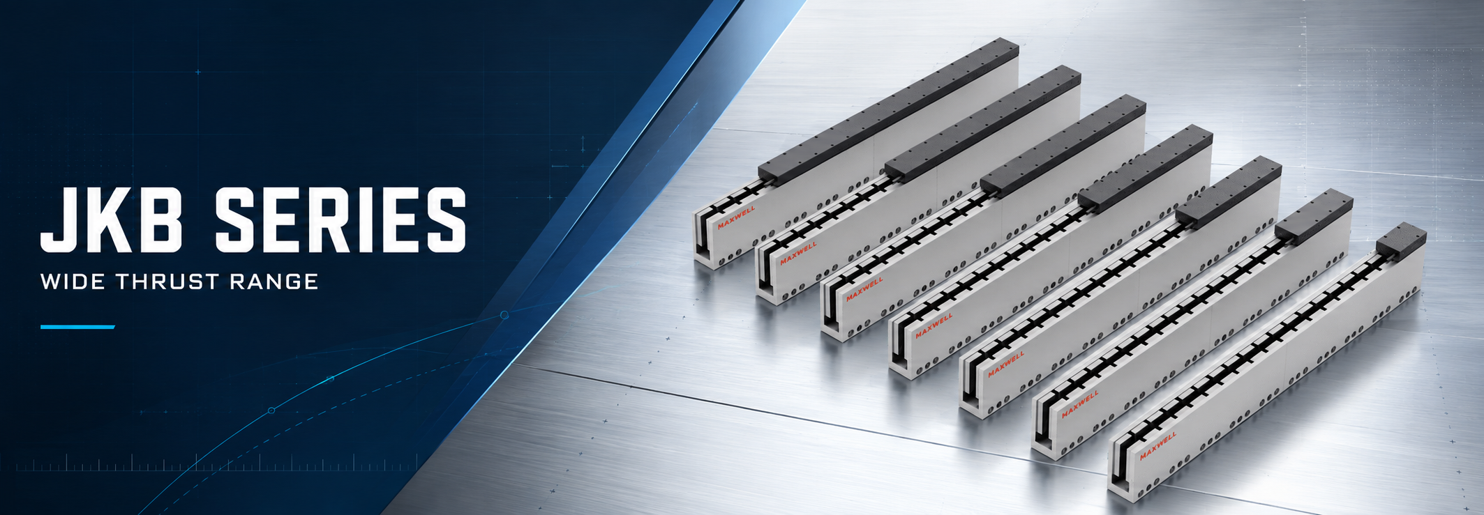
Choosing among JKB1–JKB6 requires more than finding the largest force value in the range. Each family covers multiple configurations, and the correct shortlist depends on continuous thrust, short-duration peak thrust, the complete motion cycle, cooling conditions, usable stroke, drive capacity, and the space available around the axis.
SAHO's JKB high-thrust ironless linear motor range extends from compact, low-force motion to much larger dynamic loads. Start with the real force-time requirement, remove families that cannot pass the peak or continuous check, and then compare the remaining configurations against the mechanical layout and control system. This guide supports that first-stage decision; the final model still needs to be confirmed from the current drawing and model-specific electrical and thermal data.
Product scope: JKB provides the ironless mover/coil and magnetic stator components. It is not a complete guided stage. A working axis still requires suitable guideways, a carriage and machine structure, encoder feedback, a servo drive and controller, cable management, end limits, and any required thermal system.
Where High-Force Ironless Direct Drive Fits
An ironless direct-drive motor does not place an iron core inside the moving coil. This structure avoids the normal magnetic attraction and cogging mechanism associated with an iron-core design. It can support smooth low-speed motion and predictable force changes during scanning, alignment, inspection, and settling.
Cog-free motion does not automatically create an accurate or vibration-free axis. The guide must carry the payload and moment loads, the encoder must provide suitable feedback, and the frame must remain stiff under acceleration and process force. Servo tuning, electrical noise, cable drag, air hoses, covers, and the mounting heat path can all affect the result.
JKB is a practical direction when a machine needs ironless motion and a wider force range than a small two-family series can provide. One platform may use a compact JKB family for a sensor head and a higher-force family for a gantry beam, while retaining the same general mover-and-stator integration approach.
The reason for entering the JKB range should be visible in the application data. Smooth velocity, lower guide loading from the absence of normal magnetic attraction, a demanding acceleration profile, or the need for a higher ironless force ceiling are valid reasons. Selecting JKB only because its maximum peak figure looks attractive is not.
JKB1–JKB6 Model and Thrust Range
The six JKB families overlap in published force coverage. A family range represents several configurations; it is not an adjustable rating for one fixed motor. Do not combine the shortest mover length with the family maximum thrust unless the current datasheet explicitly assigns those values to the same model code.
| JKB family | Published continuous thrust | Published peak thrust |
|---|---|---|
| JKB1 | 3–14.9 N | 11.9–59.9 N |
| JKB2 | 8.8–70.4 N | 44–352 N |
| JKB3 | 28–170 N | 144–867 N |
| JKB4 | 55–442 N | 312–2,496 N |
| JKB5 | 98–1,179 N | 707–8,489 N |
| JKB6 | 780–2,340 N | 5,400–16,200 N |
JKB1 through JKB3 provide the first screening range for compact and lower-to-medium force requirements. JKB4 through JKB6 extend the family coverage for more demanding dynamic or sustained loads. This grouping is only a starting point. A longer coil may increase available force while also changing moving mass, resistance, current demand, heat generation, and installation length.
The smallest family that reaches the required peak force is not automatically the best choice. Repeated moves with little recovery time may make continuous capability the controlling limit. A short, infrequent indexing move may place more weight on peak force, but permitted peak duration, drive current, force at speed, and the complete thermal cycle still need to pass.
How to Use the Overlapping Force Ranges
When two families satisfy the same initial force target, compare one complete operating point rather than favouring the larger number. Remove every family that misses the required peak force, continuous demand, or basic space limit. For the remaining families, compare the exact mover configuration, cooling condition, force-speed operating point, servo capacity, magnetic-track layout, guide structure, and encoder target.
This two-stage shortlist prevents detailed engineering work on a family that cannot pass the basic application limits. It also records why a candidate was retained or rejected, making later changes to payload, tooling, acceleration, or cycle time easier to review.
JKB4 Series Example
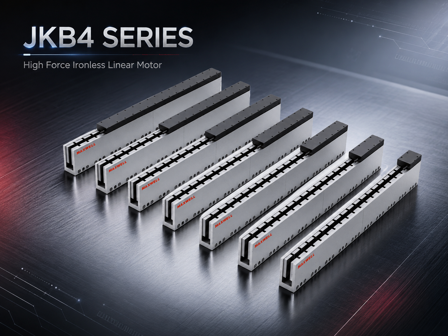
The JKB4 image shows several mover-and-stator length configurations within one family. Length changes must be matched to the exact thrust, current, cooling, and installation data rather than treated as interchangeable options.
View JKB Series Specifications
Continuous Thrust, Peak Thrust and Cooling
Continuous thrust describes the force a motor can sustain within its thermal limits under stated conditions. Peak thrust covers shorter acceleration, deceleration, reversal, or temporary process-force events. The two values must be checked separately. For the full calculation method, see SAHO's guide to continuous thrust vs peak thrust.
A practical first estimate begins with acceleration force: force equals complete moving mass multiplied by acceleration. Add guide resistance, cable and hose drag, process force, and other predictable loads. A vertical or inclined axis must also include the gravity component, powered holding demand, braking behaviour, and a separate power-off retention or safety strategy.
Record acceleration time, constant-speed travel, deceleration, processing, settling, powered dwell, true idle time, and moves per cycle. This force-time profile shows whether the highest force occurs for a fraction of a second or dominates most of production. It also prevents a peak rating from being treated as an unlimited operating point.
Thermal decision: A JKB configuration can satisfy the peak-force check and still fail in repeated production. Compare complete-cycle RMS demand with the verified continuous rating for the exact model, ambient condition, mounting heat path, and approved cooling method.
Additional cooling can improve heat removal, but it should not be assumed for every JKB family or configuration. Air lines, coolant hoses, fittings, filters, flow monitoring, service access, leakage control, and condensation prevention all affect the machine layout. SAHO's linear motor cooling guide explains how natural, air, and water cooling change the continuous-force decision.
Check the Motor and Servo Drive as One System
Published motor force is useful only when the electrical system can reach the same operating point. Check the exact winding, force constant, permitted current, bus voltage, cable length, Hall or commutation requirement, and servo-drive capacity together. An undersized drive may not supply the required peak current. At higher speed, available voltage can also limit force as back electromotive force rises. Confirm the force-speed curve instead of relying only on the low-speed thrust figure.
Worked Example: Narrowing the JKB Family Range
Consider a horizontal inspection axis with a complete moving mass of 70 kg. The most demanding move uses 6 m/s² acceleration, and predictable guide and cable resistance adds 35 N. The preliminary acceleration force is therefore 455 N. Assume the two-second cycle contains 0.2 seconds at 455 N during acceleration, 0.6 seconds at 120 N during process travel, 0.2 seconds at 455 N during deceleration, and 1.0 second of genuine unloaded rest.
| Screening result | What it means for this example |
|---|---|
| Required peak 455 N | JKB1 and JKB2 can be removed because their published family peak ranges do not reach the requirement. |
| Preliminary RMS force Approximately 214 N | JKB3 reaches the peak requirement at the family level, but its published continuous range does not reach this preliminary RMS demand. It is removed from this shortlist. |
| First family still in range JKB4 | JKB4 enters the next review stage, but the table does not confirm a final model. One exact JKB4 configuration must still pass continuous force, peak duration, cooling, force at speed, drive current, stroke, and installation checks. |
This example is a family-level screen, not a final recommendation. JKB5 or another larger option may also pass the two force thresholds, but more capacity is not automatically better. Added mover mass, current demand, heat, width, and cost can work against the machine objective. The preferred configuration is the smallest practical option that passes the complete requirement with justified engineering margin.
Mover Length, Stator Length and Installation Space
Force and length selection are connected. SAHO's website uses a “rotor length” field, while the JKB drawings describe a motor coil and magnetic track. In practical stage design, confirm the mover/coil model and the stator/magnetic-track model from the exact drawing rather than relying on the family name alone.
| Family | Published mover/coil length options (mm) | Published stator/track length options (mm) |
|---|---|---|
| JKB1 | 22 / 43 / 64 / 85 / 106 | 63 / 84 / 105 |
| JKB2 | 31 / 61 / 91 / 121 / 181 / 241 | 120 / 180 / 240 / 300 |
| JKB3 | 120 / 180 / 240 / 300 / 600 | 61 / 121 / 181 / 241 / 301 / 361 |
| JKB4 | 61 / 121 / 181 / 241 / 301 / 361 / 481 | 120 / 180 / 240 / 300 / 600 |
| JKB5 | 85 / 169 / 253 / 337 / 421 / 505 | 168 / 252 / 420 |
| JKB6 | 337 / 505 / 673 / 757 / 841 / 1,009 | 168 / 252 / 420 |
The table is an early layout reference. The exact drawing remains the controlling source because nominal family values may be rounded, while the model code defines the real coil or track dimension. For example, a nominal JKB3 coil option shown as 120 mm corresponds to a more detailed drawing dimension and model designation. Use the current 2D drawing when fixing mounting holes, air gaps, end clearances, or the machine envelope.
Do not add mover and stator lengths mechanically to calculate usable stroke. Track arrangement, coil position, end clearance, hard stops, limit sensors, homing travel, controlled stopping allowance, cable movement, and assembly tolerance all consume length. The selected drawing should define total motor coverage and safe travel.
Working travel: Include process travel, homing distance, calibration or parking travel, and controlled stopping allowance.
Motor coverage: Keep the mover within the effective magnetic-track region throughout the required stroke.
Service clearance: Reserve access for cables, sensors, cooling parts, connectors, and fasteners.
Structural clearance: Check guide blocks, encoder scale, covers, cable bend radius, and moving tooling at both travel limits.
Large Precision Platforms, Laser and Semiconductor Applications
Large precision platforms: JKB can supply direct electromagnetic force across several size classes without introducing transmission backlash in the motor force path. The guide layout must still resist pitch, yaw, and roll moments from the payload. A larger motor cannot correct a flexible base, a narrow bearing span, or a poorly supported carriage.
Laser equipment: A laser axis may combine long approach moves, repeated path reversals, controlled process speed, and quiet settling near an optical path. Include the complete moving head, beam-delivery hardware, extraction parts, covers, gas lines, and cable carrier in the calculation. SAHO's laser motion system page provides related application context.
Semiconductor and precision inspection: Ironless motion removes cogging as one disturbance source, but encoder interpolation, electrical noise, servo bandwidth, guide friction, air movement, frame modes, and changing cable forces can still affect velocity stability and settling. Define the position window, payload, move distance, measurement method, and time allowed after deceleration instead of specifying only “fast settling.”
In every application, the process condition should lead the decision. A light camera can sit on a much heavier bridge, and a small process head can carry significant service cables or hoses. Calculate the complete moving assembly and verify the structure under the real acceleration and process load.
JKB vs JKA, WKM and MNK
JKB is not a stronger replacement for every SAHO motor or stage. Compare structure, force range, vibration sensitivity, environmental exposure, and the amount of mechanical integration the machine builder wants to complete.
| Series direction | Structural focus | When it deserves consideration |
|---|---|---|
| JKB | Six-family ironless mover-and-stator range | Use when broad ironless force coverage, cog-free motion, high dynamic demand, and purpose-built stage integration lead the decision. |
| JKA ironless linear motor | JKA1 and JKA2 ironless range | Compare when low-vibration inspection or optical motion leads the requirement and the available JKA force range is sufficient. |
| WKM iron-core linear motor | Higher-force iron-core mover-and-stator range | Compare when force density and sustained heavy-duty output carry more value than an ironless structure; include magnetic attraction and guide loading in the review. |
| MNK sealed linear motor stage | Protected stage with integrated guide support | Compare when long travel, protected construction, and a more complete stage can reduce custom mechanical integration and project risk. |
Choose between JKA and JKB from the required ironless force range, available configuration, motion quality target, and installation envelope. The distinction is not “precision versus no precision.” Both require suitable guides, feedback, frame stiffness, thermal control, and tuning.
WKM changes the electromagnetic and mechanical structure. Its iron-core direction can provide useful force density, but magnetic attraction, bearing loading, working-gap control, frame stiffness, cooling, and vibration behaviour belong in the comparison.
MNK changes the integration boundary. It is a better starting point when the project needs a protected, guided stage rather than separate motor components. JKB is better suited to a machine whose guide, carriage, encoder, frame, and protection system will be designed around a purpose-built axis.
Data Required for Final JKB Selection
A useful application review starts with one complete motion profile, not a request for the strongest model. Define every moving component and the real production cycle. Keep accuracy, repeatability, velocity stability, and settling time separate because they describe different performance requirements.
Moving load and payload: Include tooling, workpiece, carriage, adapter plates, cable carrier, hoses, covers, and upper-axis mass.
Stroke and space: State usable travel, homing or calibration allowance, end clearance, available width, and total permitted axis length.
Motion target: Provide target speed, acceleration, deceleration, move distance, jerk limit where relevant, and the complete position-versus-time profile.
Cycle demand: Record cycle time, moves per minute, settling and process dwell, powered holding, true idle periods, daily operating hours, and duty cycle.
External forces: Include guide resistance, cable or hose drag, gravity, process force, disturbance load, and when each force acts.
Motion quality: Separate required accuracy, repeatability, velocity smoothness, allowable settling time, and measurement conditions.
Installation direction: Identify horizontal, vertical, inclined, inverted, gantry, side-mounted, or stacked-axis operation.
Cooling and environment: Describe local temperature, enclosure, airflow, contamination, clean-area needs, mounting heat path, and available cooling utilities.
Feedback and control: List encoder type and resolution, servo drive, bus voltage, current capacity, controller, communication requirements, and existing cable limits.
Add a sketch showing the centre of gravity, guide spacing, process-force point, cable exit, cooling connections, and motor envelope. These details expose moment loads and packaging conflicts that a payload number cannot show. They also help separate a motor-sizing problem from a guide or frame problem.
For broader axis planning, review SAHO's linear motion solutions for industrial automation. It helps place direct drive beside belt, screw, and electric-cylinder options before one technology is applied to every axis.
Frequently Asked Questions
Does every mover length provide the maximum thrust shown for its JKB family?
No. The published minimum-to-maximum range covers multiple configurations. Match the required force to one exact mover/coil model, winding, cooling condition, and drive operating point. Do not assign the family maximum to every listed length.
Can the family table confirm a final JKB model?
No. It can remove families that miss a basic force threshold and identify candidates for detailed review. Final confirmation still needs model-specific continuous and peak data, permitted peak duration, force at speed, cooling, drive current, bus voltage, mover and track length, working gap, cable routing, and installation clearance.
How should two JKB families with overlapping force ranges be compared?
Compare the exact configurations that pass the same peak and continuous requirement. Then review moving mass, physical width and length, current demand, thermal margin, available cooling, force at speed, and service access. The better choice is the configuration that meets the requirement without unnecessary size or electrical demand.
Can strong JKB thrust be treated as vibration-free motion?
No. The ironless structure removes iron-core cogging and normal magnetic attraction, but guide variation, frame resonance, encoder noise, cable drag, cooling lines, control tuning, and external process forces can still disturb the axis. Validate motion quality on the complete mechanical and control system.
When should WKM or MNK be considered instead?
Compare WKM when an iron-core structure and higher force density fit the machine better. Compare MNK when long travel, protected construction, and integrated guide support reduce unnecessary custom integration. Retain JKB when broad ironless force coverage and a purpose-built stage are central to the design.
Turn the Shortlist into an Application Review
A JKB shortlist becomes reliable only after force, heat, space, feedback, and structure are checked under the same machine requirement. Close the gap between a family comparison and a buildable axis with three actions:
Calculate peak and complete-cycle RMS demand from the full moving mass and every segment of the production cycle.
Check motor coverage, guide spacing, cable routing, cooling access, end limits, and service clearance on one layout.
Define measurable accuracy, repeatability, velocity, and settling criteria before final sizing and tuning.
For a JKB model review, submit moving load, payload variation, stroke, target speed, acceleration, complete cycle time, duty cycle, external force, required accuracy or repeatability, installation direction, cooling conditions, environment, encoder, servo drive, and controller information. If a layout drawing or force-time profile is available, mention it in the request so the engineering team can confirm how to provide the file.