

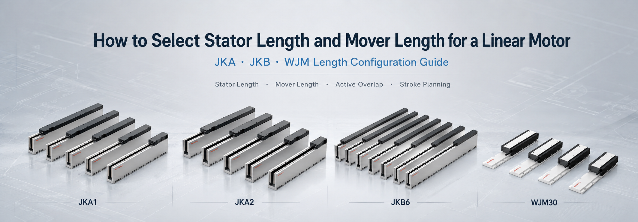
Selecting linear motor stator length starts with working stroke, but stroke alone does not define the required hardware. The stationary active section must also preserve effective magnetic overlap at both travel limits. In addition, the finished axis needs room for end margins, sensors, mechanical stops, cable routing, bearing blocks, covers, and assembly tolerances. A track that merely matches the commanded travel can therefore leave part of the motion range without sufficient force or safe stopping space.
The method separates commanded travel, active overlap, and external clearance. It also identifies the moving component, because moving coils and moving magnet tracks create different cable and space demands.
Core sizing rule: do not approve motor length from nominal stroke alone. Check endpoint overlap and all space beyond the active motion zone.
Stator, Mover and Active Overlap Defined
A linear motor produces force through the interaction of a magnetic field and an energized winding. One element remains fixed to the machine base, while the other travels with the carriage or payload. Product literature may use terms such as stator, magnet track, coil unit, rotor, motor, or mover. Because naming can vary between structures, the installation drawing should identify the fixed and moving parts rather than relying on one label.
In this guide, stator length means the stationary active length available along the travel direction. Mover length means the length of the traveling motor element. Active overlap means the portion of the two active elements that remains magnetically engaged at a given carriage position. The selected motor must keep at least the required overlap throughout usable travel.
| Dimension | What it represents | Why it affects selection |
|---|---|---|
| Working stroke | Distance between required process positions | Defines commanded travel, not total track length |
| Active overlap | Required engagement between active motor elements | Protects force production at each travel limit |
| Controlled travel allowance | Homing, deceleration, recovery, or setup movement outside the process stroke | Extends commanded motor travel and normally requires active track coverage |
| External mechanical clearance | Space for sensors, stops, connectors, covers, assembly variation, and service access | Increases the machine envelope but does not always require equal added active stator length |
| Mechanical envelope | Total occupied length of the complete axis | Determines whether the selected layout fits the machine frame |
For low-vibration positioning, the SAHO low-vibration ironless linear motor series provides separate moving and stationary elements in several published length options. The component choice still depends on the endpoint overlap shown in the axis drawing. Smooth motor behavior cannot correct a layout that loses active engagement near an end position.
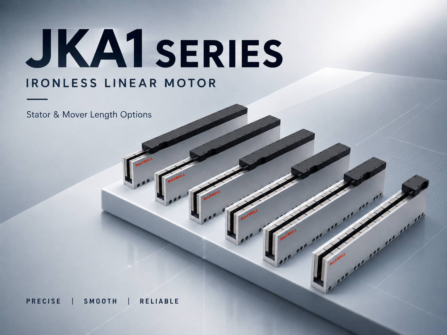
JKA1 product configurations illustrate why moving-element length and stationary active length must be selected together.
How Linear Motor Stator Length Determines Available Stroke
For a common fixed-track layout, available stroke depends on commanded travel and the overlap reserved at each endpoint. The relationship below supports initial layout work but does not replace the model drawing.
Commanded motor travel = process stroke + justified homing travel + controlled overtravel + required recovery travel
Preliminary fixed-track relationship: the stationary active length must cover the full commanded motor travel plus the manufacturer-defined active mover coverage required at an endpoint.
Overall axis envelope: verify the active motor assembly together with external sensor, stop, connector, cable, cover, bearing, tolerance, and service clearances.
Only movement that requires controlled electromagnetic force belongs in commanded motor travel. Sensor brackets, hard stops, connectors, covers, bearing clearances, and service access can increase total machine length without requiring the same increase in active stator length. Keeping these values separate prevents an oversized track while preserving the space needed for safe integration.
Required coverage is model-specific and must come from the selected drawing or engineering confirmation. If rated force must remain available over the full stroke, the complete approved active mover length normally needs to remain engaged unless the drawing explicitly permits partial overlap and defines the resulting force. Do not substitute overall mover length: end plates, connectors, cable exits, and other inactive sections may add physical length without contributing to force. Confirm the reference datums and length relationship for the exact JKA, JKB, WJM, or other selected model before releasing the drawing.
Likewise, physical stator length may not equal active stator length. Mounting holes, joining gaps, protective end pieces, and assembly interfaces can change the usable field zone. For that reason, a drawing should show the motor reference datum and the active start and active end positions. Overall dimensions alone do not reveal whether commanded travel remains inside the valid force-producing area.
Start with process positions, not nominal axis travel
Measure working stroke between actual process points. Loading, inspection, tool-change, or calibration positions outside the main production zone still belong in commanded travel when the axis reaches them during normal operation.
Add controlled overtravel only where homing, deceleration, recovery, or setup requires it. Do not treat this movement as crash space. Normal servo travel should end before the mechanical stop and preserve a separate safety reserve.
Check force at both endpoints
Endpoint force matters whenever acceleration, settling, or holding occurs near a travel limit. A carriage may reach the position geometrically yet lack the intended force margin if active overlap has fallen below the approved value. The risk becomes more important when the payload changes, the axis operates vertically, or the process requires rapid reversal close to an endpoint.
A practical drawing review marks the mover at the left limit, center position, and right limit. Each view should show active overlap, cable condition, sensor state, stop clearance, and bearing-block position. This simple three-position check exposes many layout errors before detailed frame drawings are released.
Convert Working Stroke Into Required Track Length
A reliable stroke calculation follows the physical motion path. Begin with the distance between required process positions. Then add homing and controlled overtravel. After that, reserve the model-specific active overlap and functional end margins. The resulting active-length requirement can be matched to available stator or magnet-track sections.
Define the working coordinates. Record every production, loading, inspection, calibration, and maintenance position that the axis must reach.
Set the usable stroke. Measure between the outermost required coordinates rather than using an approximate machine width.
Add controlled travel. Include only justified homing, deceleration, recovery, or setup movement.
Apply the approved overlap. Use the active overlap requirement for the selected motor, not a generic allowance.
Add end functions. Reserve separate room for sensors, hard stops, cable exits, covers, and service access.
Match standard sections. Select a published length combination that meets or exceeds the calculated active requirement, then verify the final drawing.
Standard track sections may need to be arranged in sequence for a longer axis. In that case, the joint location deserves attention. A joint should not be assumed to behave as continuous active length unless the product design and assembly method support that interpretation. Flatness, alignment, pitch continuity, fastening sequence, and any specified joining gap must follow the applicable drawing.
The moving structure also changes the envelope calculation. With a moving coil and fixed magnet track, the power and feedback cable package travels with the carriage. With a moving magnet assembly and fixed coil, the moving mass and structural length can increase even though cable motion decreases. The preferred arrangement depends on payload, acceleration, cooling, cable life, contamination control, and frame geometry.
How to Select Mover Length from Force and Thermal Demand
Stator or track length mainly answers how far the motor must remain active. Mover length answers a different question: which exact motor configuration can produce the required peak and continuous force within the available space and thermal conditions. Two axes with the same stroke can therefore use different mover lengths when their moving mass, acceleration, external load, duty cycle, or cooling arrangement differs.
Preliminary force screen: required axis force = complete moving mass × acceleration + guide resistance + cable drag + process force + any applicable gravity component. Check the short peak event separately from the repeating continuous or RMS demand.
When the force profile has not yet been calculated, first work through linear motor sizing for payload, acceleration and cycle time. That calculation narrows the valid mover options before stator length is matched to the required travel.
Begin with the complete moving assembly, not the nominal payload alone. Include the carriage plate, mover, tooling, encoder head where applicable, brackets, covers, the moving part of the cable carrier, and any hoses or process services. For vertical or inclined motion, add the gravity component and define a separate power-off holding or counterbalance method.
Within one motor family, a longer mover or motor option may provide a different force and thermal configuration, but it is not automatically the better choice. Additional length can increase moving mass, current and cooling requirements, cable demand, and the occupied carriage envelope. Compare one exact mover length against its published continuous thrust, peak thrust, permitted peak duration, force at operating speed, cooling condition, drive limits, and mounting space. Do not combine the maximum force of one configuration with the dimensions or cooling assumptions of another.
Keep the two length decisions separate Mover length: shortlist from force, duty cycle, thermal conditions, moving mass, drive capability, and available carriage space.
Stator length: determine from commanded travel, the approved active mover coverage at both endpoints, section joints, and model-specific reference datums.
Final axis length: add guides, sensors, stops, cable exits, covers, tolerances, and service clearance as physical envelope items.
If more than one mover length passes the force and thermal checks, compare the finished move-and-settle result rather than choosing only the largest force reserve. A heavier mover can meet the thrust requirement yet demand a stiffer base, stronger guide support, different servo capacity, or more cooling. Final selection must use the current model datasheet and engineering drawing.
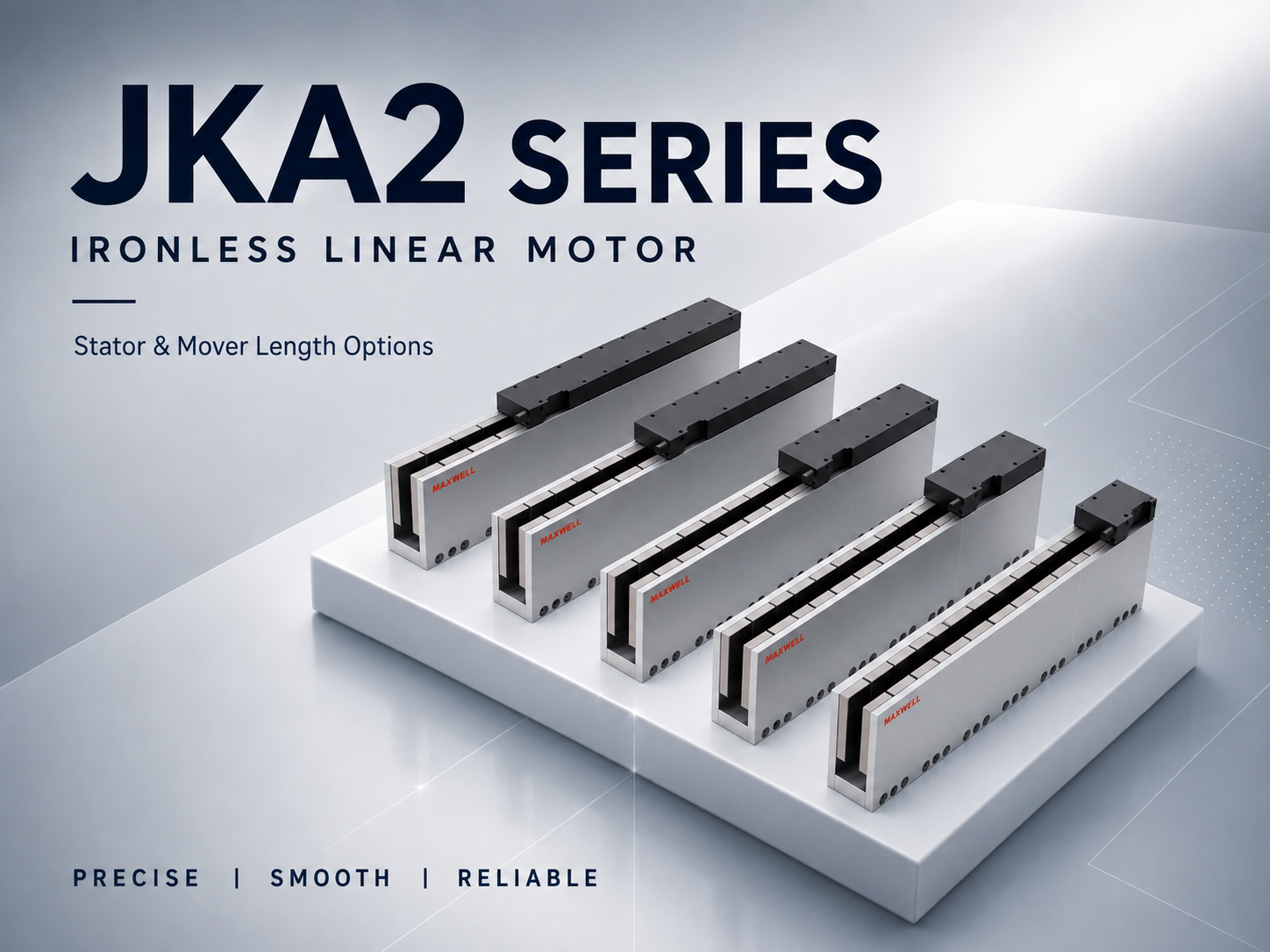
JKA2 configurations show moving-element and stator options for stroke and overlap planning.
End Margins, Sensors, Cable Space and Mechanical Stops
End margin is not one universal number. It should be divided into controlled travel and external hardware clearance. Homing, recovery, or deceleration movement normally needs active motor coverage. By contrast, sensor brackets, hard stops, connectors, covers, and service space may extend the total axis envelope without adding the same amount of active track.
A short axis can still need meaningful external clearance because brackets, cable connectors, stop blocks, and mounting tools occupy real space. Meanwhile, a long axis may need additional controlled deceleration travel because stored kinetic energy grows with speed and moving mass. Both values belong on the endpoint drawing, but they should remain separate in the length calculation.
Home and limit sensor placement
The home sensor should provide a repeatable reference without forcing the mover into the mechanical end region. Positive and negative limit sensors should trigger early enough for the controller to stop motion under the approved speed and load conditions. Their brackets must remain adjustable and accessible after covers are installed.
Sensor targets also consume length. A flag may project beyond the carriage, while a compact target may require a narrow sensing gap. Draw both the sensor body and target at each endpoint. Otherwise, a target can collide with a bracket even when the nominal carriage coordinate appears safe.
Mechanical stop and braking reserve
Mechanical stops protect the structure after control protection has failed or abnormal motion has occurred. They should not serve as routine positioning references. The stop location must account for bumper compression, carriage projection, bearing-block clearance, tool overhang, and the payload's own geometry.
A stop also needs a load path into the frame. Placing a small stop at the edge of a thin cover may create damage without reliably arresting the axis. Therefore, the travel drawing and frame drawing should share the same endpoint datum and stopping direction.
Cable exit and carrier travel
Cable space must be checked in three dimensions. The motor power cable, encoder cable, sensor wiring, cooling lines, and process services may leave the mover at different heights. Their bend radii and strain-relief points can extend beyond the motor body and reduce usable room near an end plate.
For long stroke, the cable carrier also creates moving resistance. A crowded carrier can twist cables or apply side load to the carriage. Accordingly, the layout should show carrier length, fixed-end position, moving-end position, bend radius, fill level, and clearance through the full stroke.
Drawing check: if a cable connector, sensor bracket, stop block, cover, or bearing block is absent from the endpoint view, the stated usable stroke is not ready for approval.
Single-Mover and Multi-Mover Layouts
A single-mover axis has one moving motor element and one controlled carriage. Its track requirement follows the outermost process positions plus overlap and end functions. Even in this simpler arrangement, payload overhang can make the carriage envelope longer than the motor mover. The motion drawing should therefore use the largest moving projection, not only the motor body.
A multi-mover concept places two or more independently controlled carriages along a common active path. This can support parallel handling, independent processing, or shorter transfer cycles. However, a shared track does not automatically mean that every motor series permits any mover count or spacing. Product compatibility, drive architecture, encoder arrangement, collision logic, thermal loading, and cable routing require confirmation.
Add mover-to-mover spacing to the length equation
For two movers, the outer process coordinates do not tell the whole story. The layout must include each mover's physical length, payload overhang, minimum operating separation, collision reserve, and any zone where one mover must pass or wait. If the movers never cross, their assigned operating zones can be defined separately. If process logic changes those zones, the longest credible arrangement should govern the track envelope.
In a laser motion system, for example, one carriage may position a workpiece while another handles measurement or transfer. Length selection should reflect the complete process sequence, including loading clearance and safe separation. Designing only around the cutting or marking stroke can omit essential non-process movement.
JKA, JKB and WJM Length Options
Length cannot be selected independently from motor structure and force requirements. SAHO positions JKA and JKB as ironless direct-drive ranges, while WJM uses a compact iron-core structure. JKA emphasizes smooth, cog-free, low-vibration motion for inspection, optical, laser, and semiconductor equipment. JKB extends ironless selection across a broader thrust range for precision stages and automation. WJM focuses on compact iron-core motion where stable thrust and fast response are important; the WJM linear motor selection guide provides the model-level force, width, duty-cycle, and integration context behind those length options.
JKA, JKB, and WJM are used here as length-selection examples, not as a complete comparison of every SAHO linear motor family. If the choice is still between a smooth ironless structure and a higher-force-density iron-core structure, review the ironless vs iron-core linear motor comparison before fixing the series. If none of these ranges meets the verified force, thermal, or integration requirement, compare the other applicable motor or complete-stage families before fixing the axis architecture.
The high thrust ironless linear motor range is relevant when an ironless structure is preferred but the load and motion profile require more force coverage than a low-vibration selection alone provides. By contrast, the compact iron core linear motor range may suit a tighter installation envelope with stable thrust. WJM should not be confused with WKM: WJM is positioned for compact precision motion, whereas WKM is the high-force, heavy-duty iron-core range.
| Series | Published length information | Selection emphasis |
|---|---|---|
| JKA | The series page lists several moving-element lengths and stator options for JKA1 and JKA2. It labels the moving length as rotor length. | Low vibration, cog-free movement, stable settling, and precision positioning |
| JKB | The series page lists model-specific moving-element and stator lengths across JKB1 through JKB6. Available combinations vary by model. | Wide thrust coverage with smooth ironless direct drive for precision stages |
| WJM | The series page publishes motor lengths of 56, 96, and 176 mm and stator sections of 80, 200, and 400 mm for WJM30, WJM50, WJM80, and WJM100. | Compact iron-core structure, stable thrust, and fast-response precision motion |
Published lengths identify standard components, not usable stroke or continuous-force capability. The final pair must satisfy overlap, endpoint force, duty cycle, cooling, mounting, cable exit, guide spacing, and frame clearance. Confirm continuous thrust and cooling for the exact model and motion cycle.
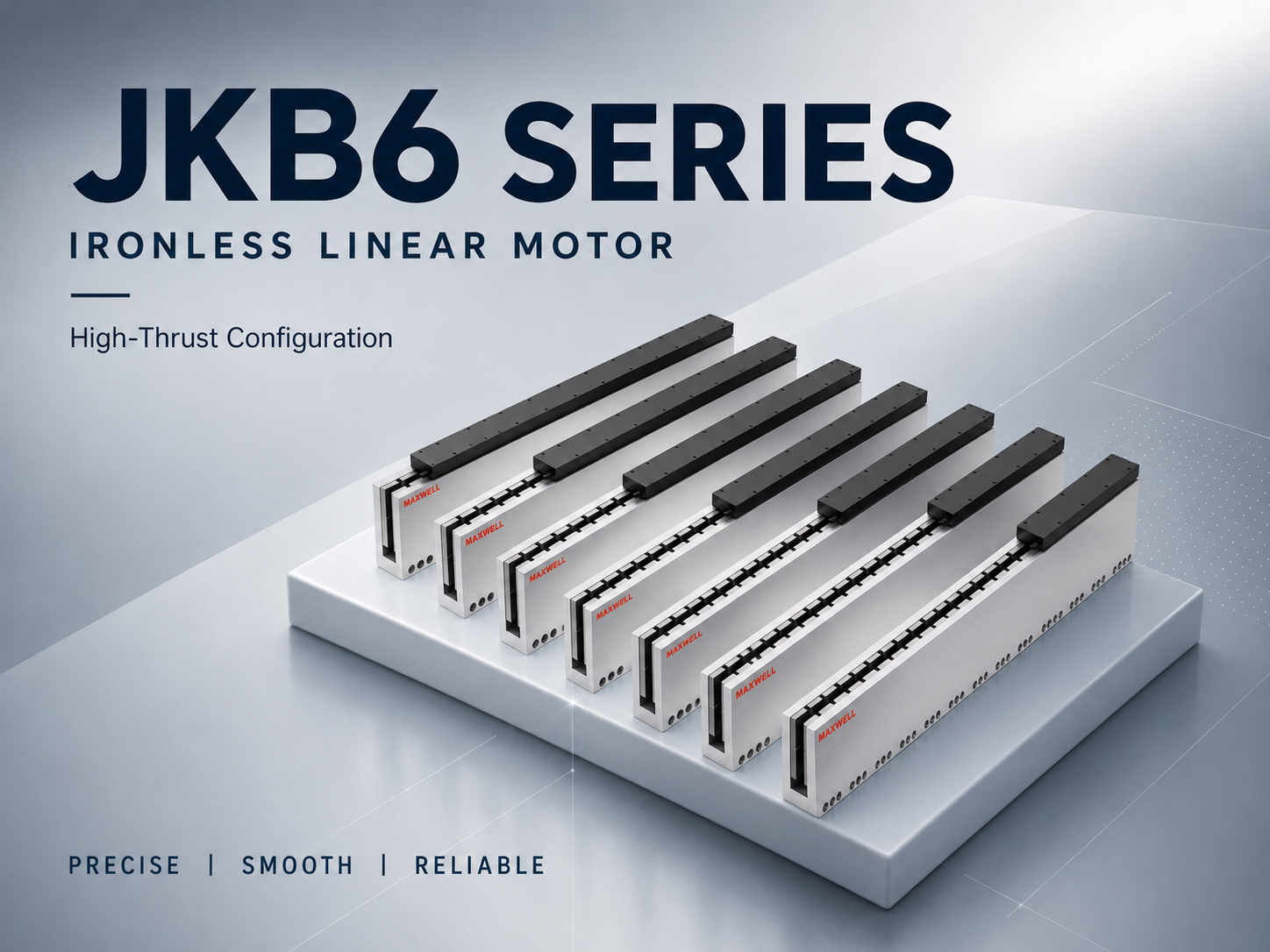
JKB6 shows longer ironless configurations that require a carefully planned active track.
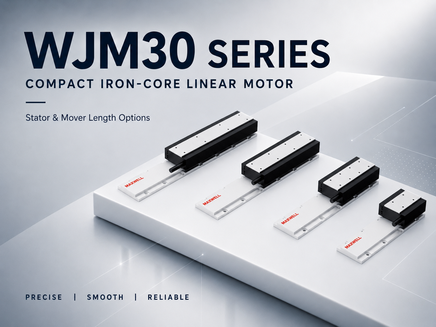
WJM30 illustrates the compact iron-core format and its published length combinations.
What a Reliable Length Decision Looks Like
In a real machine, the shortest standard combination is not automatically the best fit. The useful choice is the one that delivers the required motion while leaving the carriage, cables, sensors, stops, guides, and service points workable. The following questions keep that decision tied to the machine rather than to one catalogue dimension.
What must the axis do during a complete cycle?
A cutting, inspection, handling, or positioning axis rarely moves only between two process points. Loading, calibration, homing, recovery, and parking positions can extend the commanded travel. Map the complete cycle with the moving load, speed, acceleration, duty cycle, installation direction, and any operation performed near an endpoint. That reveals both the real force demand and the travel that needs active motor coverage.
Which part reaches the frame limit first?
The motor body is not always the longest moving feature. A laser head, camera bracket, fixture, cable outlet, encoder head, or offset payload may reach a cover or frame member first. Treat the carriage and everything attached to it as one moving envelope, then mark the center of gravity and guide-bearing locations. This avoids approving a motor length that works on paper while the tooling loses usable travel.
Which extra distance needs force, and which only needs space?
Homing, recovery, and controlled overtravel normally belong in commanded motor travel because the mover still needs controlled force there. A sensor bracket, stop block, connector, cover, or maintenance tool may only enlarge the physical envelope. Keeping those two groups separate prevents both mistakes: buying unnecessary active track and leaving too little room to build or service the axis.
Which standard component pair fits the real priority?
JKA, JKB, and WJM do not represent one simple size ladder. First shortlist the structure and mover length that meet force, smoothness, thermal, and installation needs. Then match a stator arrangement to the commanded travel and endpoint coverage. If two combinations work, compare moving mass, settling behavior, cooling, cable motion, mounting space, and endpoint access instead of choosing only the shortest or strongest option.
What changes at the two ends of travel?
Place the complete moving assembly at the negative limit, process center, and positive limit. At each position, check active coverage, the nearest obstruction, sensor state, stop clearance, cable condition, and usable service space. This three-position review often exposes a problem that a single overall-length dimension hides. A vertical axis also needs a defined power-loss state and a holding or counterbalance concept.
Before releasing the drawing, confirm: fixed and moving components are named; active length is distinguished from overall length; both endpoint overlaps are shown; sensors and stops have separate clearances; the cable path is drawn through full travel; guide blocks remain within rail limits; and the selected standard lengths match the latest product drawing.
Review base stiffness, guides, encoder mounting, covers, and drive integration in linear axis design for industrial automation. A correct motor length still needs a complete frame, guide, and feedback layout.
Frequently Asked Questions
Is stator length the same as usable stroke?
No. Usable stroke is the process distance the axis must deliver. The selected stator arrangement must also cover justified homing or recovery movement and preserve the active mover coverage required by the current SAHO model drawing. Sensors, stops, connectors, and service access may make the complete axis longer again without requiring the same amount of additional active track.
Does a longer mover create a longer stroke?
Not by itself. Mover length is mainly part of the force and thermal configuration, while the stator arrangement mainly supports travel. A longer mover may provide a different thrust option within a JKA, JKB, or WJM family, but it can also add moving mass and installation demand. Confirm the force rating and dimensions of the exact configuration rather than assuming that longer means more travel.
Should sensor and mechanical-stop space be added to stator length?
Only when that distance is part of controlled motor travel. A home or recovery move that needs electromagnetic force normally requires active coverage. A bracket, hard stop, connector, cover, or tool-access zone may only increase the finished machine envelope. Show both values separately on the endpoint drawing.
Can JKA, JKB, or WJM use more than one mover on one stator path?
Do not assume compatibility from the shared-track concept alone. Ask SAHO to confirm the permitted mover count and spacing for the exact model, together with encoder channels, drive architecture, homing logic, collision control, cable routing, and thermal loading.
What should be sent to SAHO before confirming the lengths?
Send the complete moving mass, working stroke, speed, acceleration, cycle timing, installation direction, required accuracy or repeatability, available axis envelope, cable exit direction, cooling conditions, and a sketch showing both endpoints. If the axis has more than one mover, include the required working zones and minimum separation.
When the Shortest Combination Is Not the Best Choice
A compact layout can look efficient until the connector reaches the end plate, the sensor target has no adjustment room, or the cable carrier tightens near the positive limit. The opposite problem is an unnecessarily long track selected by adding every bracket and stop allowance to the active length. Both outcomes come from treating one overall dimension as if it answered every design question.
The better choice leaves enough active coverage for the real motion, enough mover capability for the force and duty cycle, and enough physical space to assemble, stop, cable, cover, and service the axis. Before purchase, compare the selected JKA, JKB, or WJM component pair with the current product drawing at both travel limits—not only with a nominal stroke value.
Prepare the Data for Length and Motor Sizing
For a useful sizing review, submit the moving load or payload, required stroke, target speed, acceleration, cycle time or duty cycle, required accuracy or repeatability, installation direction, cooling and environmental conditions, plus encoder and controller information. A travel sketch should also show the available machine envelope, fixed and moving elements, cable exit direction, sensor locations, and any multi-mover spacing requirement.
With those inputs, the linear motor stator length, mover configuration, active overlap, and end allowances can be checked as one system. Contact SAHO for linear motor sizing support and include the motion data and drawing in the request.